Nibbler assembly for punch press and method of forming elongated hole in sheet material

a technology of elongated hole and nibbler, which is applied in the direction of shearing apparatus, metal working apparatus, manufacturing tools, etc., can solve the problems of reducing process efficiency, deteriorating appearance, and uncomfortable touch, and achieve the effect of achieving more efficiency in the operation of nibbler

Active Publication Date: 2014-10-21
MURATA MASCH LTD
View PDF11 Cites 3 Cited by
  • Summary
  • Abstract
  • Description
  • Claims
  • Application Information

AI Technical Summary

Benefits of technology

[0012]Preferred embodiments of the present invention provide an inexpensive nibbler assembly for a punch press that can perform a nibbling operation with more efficiency and can perform smooth finishing of the overlaps between successive punched holes.
[0017]The seam-like portion formed on the shear droop surface can be minimized when performing a nibbling operation of punching in the sheet material successive holes that at least partially have an overlap with each other. This advantage is derived by the combination of the following two effects. Firstly, the portion of the sheet material that is adjacent the edge of a previously punched hole, which, in turn, is more proximal to the upstream of the feed direction, is rendered to be the processed portion that is deformed downwardly. Secondly, the shear droop surface is formed at the corners of the previously punched hole, which corners are more proximal to the upstream of the feed direction. Also, since a fracture surface is formed at each corner of the previous punched hole, no burnished or sheared surface, when the next hole is punched, remains at the lower portion of the sheared surface, thereby not forming the aforementioned type of protrusion on the sheared surface. Furthermore, since such a fracture surface is formed at each corner of the previously punched hole, even when the fracture surface is rubbed and stretched downwardly by a side surface of the punch during punching process, an amount of protrusion from the bottom surface of the sheet material is limited. As a result, a protrusion or prong protruding from the bottom surface of the sheet material can be minimized.
[0019]In a nibbling operation using this nibbler assembly, a smaller overlap margin can be achieved between the successive holes along the feed direction, compared with a conventional nibbler assembly having the slant cutter blade mentioned above, thereby resulting in improved process efficiency. Also, the nibbler assembly of the present preferred embodiment, as compared with those described in Japanese Patent No. 3401908 and Japanese Patent No. 3960066, has a simplified construction and can be manufactured with low cost.
[0021]With such a construction, the cut surface of the corner of a previously punched hole will not be rubbed and stretched downwardly by a side surface of the punch. Therefore, the protrusion from the bottom surface of the sheet material can be further minimized.
[0025]For example, such a punch may be used to carry out a nibbling operation in combination with a die that includes a through opening, with the through opening of an oblong configuration as viewed along the vertical direction. In such a case, the same advantages as the nibbling operation with the nibbler assembly according to the above-described preferred embodiment of the present invention can be achieved.

Problems solved by technology

Such a conventional process may leave a seam-like portion at one end of the overlap between the successive holes, which may deteriorate an appearance or may cause an uncomfortable touch.
Manual treatments not only lead to a variation in the finishing quality due to the skill of attendant workers but also involve more process steps, thereby lowering the process efficiency.
However, the kind of punch used in these techniques has a complex shape and is accordingly expensive.
Also, since the sheet material is not punched out by the slant cutter blade section, a hole that can be punched per stroke is of a limited length and accordingly, the process efficiency is low.
Furthermore, complicated control must be implemented to assure a fine adjustment of the stroke length of the punch.

Method used


Image

  • Nibbler assembly for punch press and method of forming elongated hole in sheet material
  • Nibbler assembly for punch press and method of forming elongated hole in sheet material
  • Nibbler assembly for punch press and method of forming elongated hole in sheet material

Examples


Embodiment Construction

[0051]Preferred embodiments of the present invention will be described in connection with the drawings.

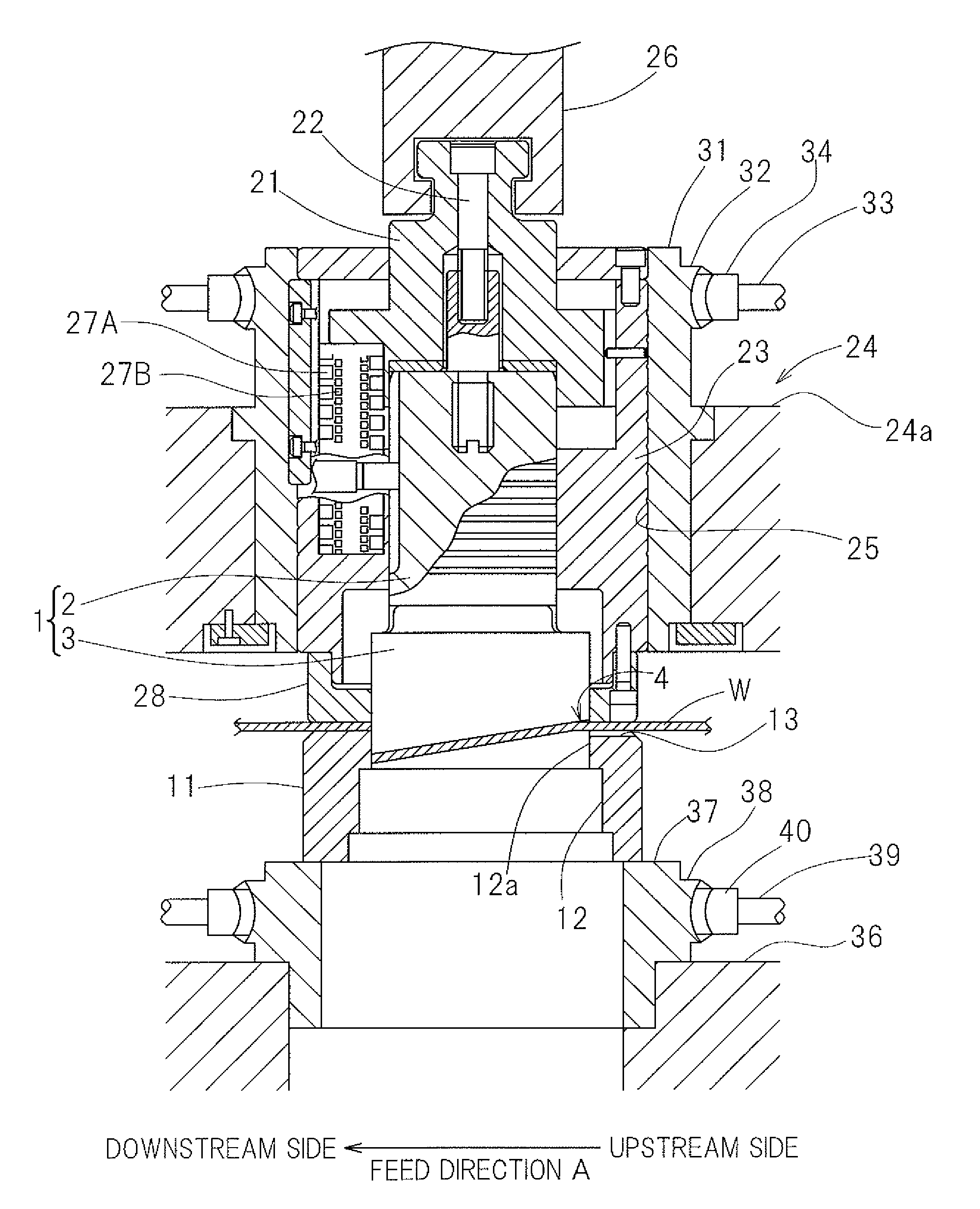
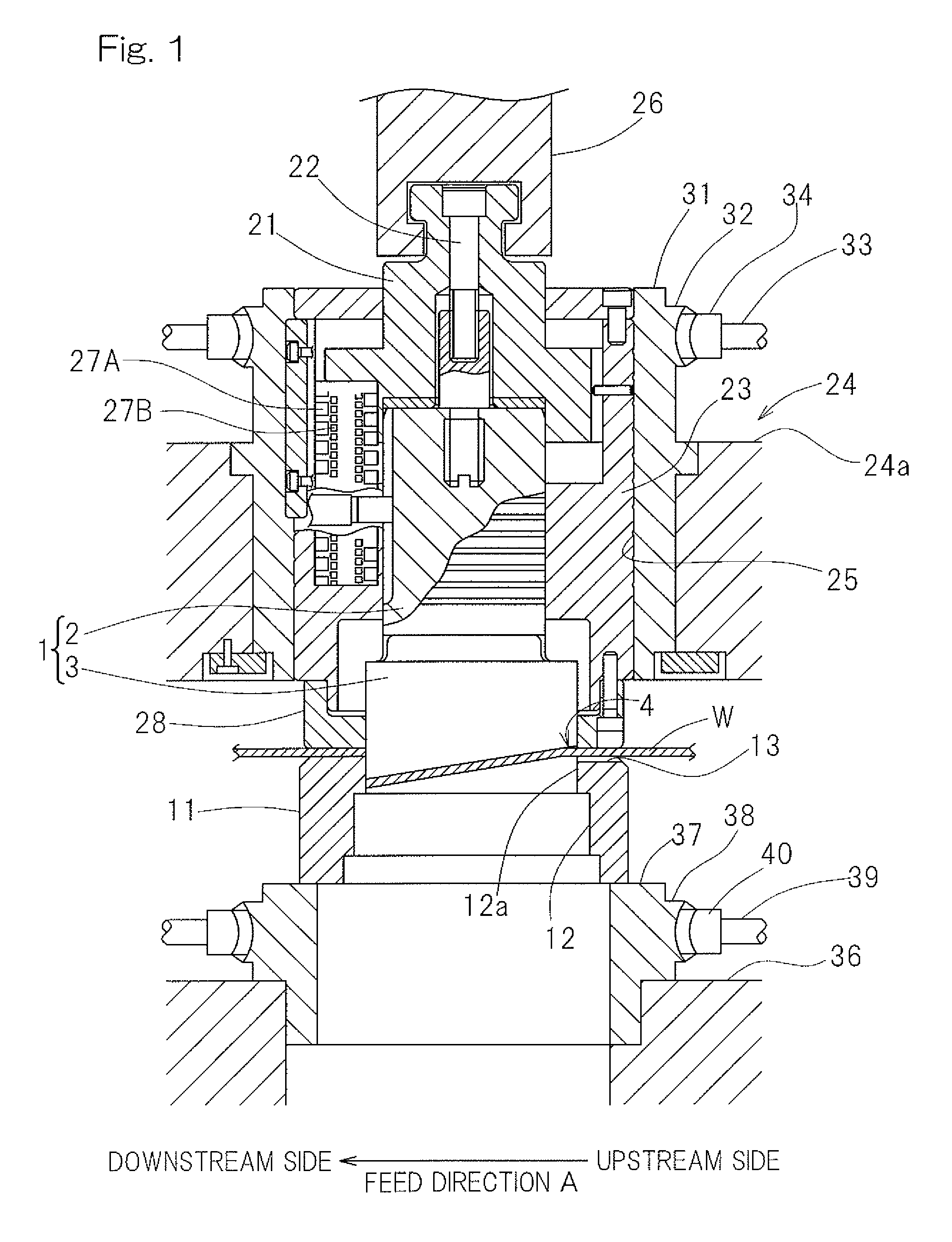
[0052]FIG. 1 shows amount system of a punch press to which a nibbler assembly according to a first preferred embodiment of the present invention is mounted. The nibbler assembly includes a punch 1 and a die 11, and a punching operation is carried out by positioning a sheet material Won the die 11 such that the sheet material W extends in a horizontal plane and then lowering the punch 1 against the sheet material W.

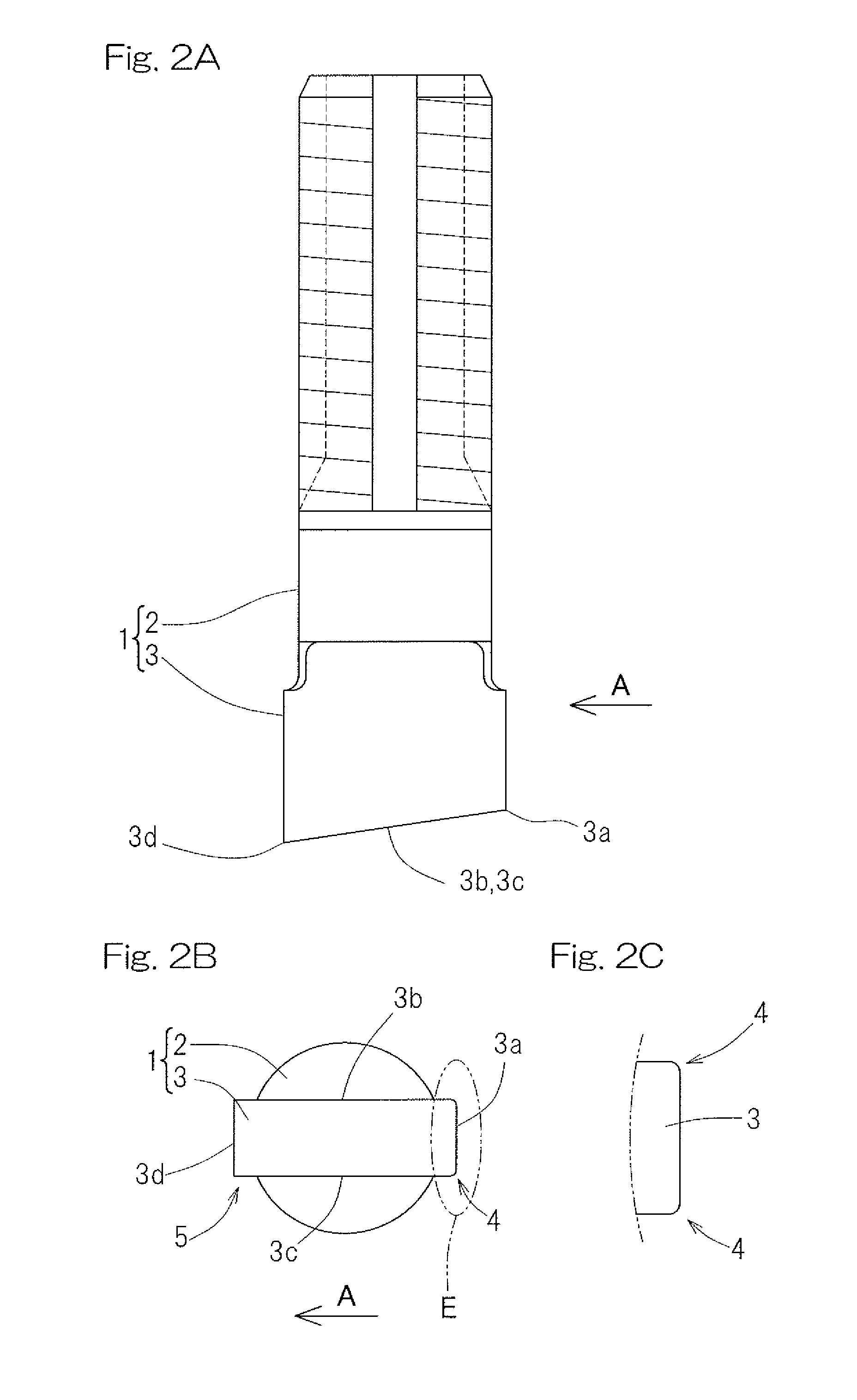
[0053]As shown in FIG. 2A and FIG. 2B, the punch 1 includes a haft 2 and a blade 3 provided at a lower end of the haft 2. The blade 3 preferably is oblong, for example, rectangular or substantially rectangular, in a cross sectional shape thereof, and includes a bottom surface that is inclined upwardly towards the upstream (the right side of FIG. 2A) of a feed direction A in which the sheet material W is fed. The bottom surface of the blade 3 has a constant height level wi...


PUM

PropertyMeasurementUnit
shapeaaaaaaaaaa
width dimensionaaaaaaaaaa
distanceaaaaaaaaaa

Abstract

A nibbler assembly includes a punch and a die. The die includes a through opening formed therein, which opening has an oblong configuration as viewed along a vertical direction. The die includes an upper surface including a recess extending from an upper peripheral portion of the through opening at an upstream side of a feed direction towards the upstream of the feed direction. The recess is dented downwardly relative to other portions of the upper surface. The punch includes a blade substantially matching in shape with the through opening. The blade includes an upstream end portion in the feed direction provided with opposite corners each having an arcuate shape as viewed along the vertical direction. The punch and the die are operable to punch successive holes that at least partially overlap along the feed direction so as to form an elongated hole in a sheet material.

Description

CROSS REFERENCE TO THE RELATED APPLICATION[0001]This application is based on and claims convention priority to Japanese patent application No. 2011-142536, filed Jun. 28, 2011, the entire disclosure of which is herein incorporated by reference as a part of this application.BACKGROUND OF THE INVENTION[0002]1. Field of the Invention[0003]The present invention relates to a nibbler assembly for a punch press to perform a nibbling operation performed on a sheet material, a method of forming an elongated hole in the sheet material with such a nibbler assembly, and a punch for a punch press to perform a nibbling operation to the sheet material.[0004]2. Description of the Related Art[0005]In a nibbling operation performed on a sheet material with a punch press, a conventional process may include the use of a die and a punch to punch a plurality of successive holes that at least partially overlap with each other. The die may include a through opening formed therein and having an oblong confi...

Claims


Application Information

Patent Timeline
Patent Type & Authority Patents(United States)
IPC IPC(8): B21D28/16B21D28/00B23D27/00
CPCB21D28/16B23D27/00Y10T83/9425Y10T83/8854Y10T83/9428Y10T83/0572Y10T83/9435
Inventor MATSUMURA, KOHEI
Owner MURATA MASCH LTD
Why Eureka
Try Eureka