Mounting structure for in-wheel motor system

a technology of in-wheel motors and mounting structures, which is applied in the direction of motor deposition, propulsion parts, vehicle components, etc., can solve the problems of poor drivability of vehicles, inability to support the fastened in-wheel motor system, and inefficient use of space, so as to prevent damage to in-wheel motors, improve strength, and stabilize the connection of in-wheel motors

Active Publication Date: 2014-10-21
HL MANDO CORP
View PDF36 Cites 23 Cited by
  • Summary
  • Abstract
  • Description
  • Claims
  • Application Information

AI Technical Summary

Benefits of technology

[0014]Therefore, it is an aspect of the present invention to provide a mounting structure for an in-wheel motor system which may provide a miniaturized compact in-wheel motor system to make the most use of the space in a wheel to prevent damage to an in-wheel motor and to ensure stable connection of the in-wheel motor system by improving the strength to support fastening of the in-wheel motor to a vehicle.
[0015]It is another aspect of the present invention to provide a mounting structure for an in-wheel motor system which may improve efficiency of installation and detachment of the in-wheel motor system by allowing the in-wheel motor to be easily installed at and detached from a vehicle, without interference with other components.

Problems solved by technology

In such an in-wheel motor system, the reducer 30 needs to be provided to increase torque of the in-wheel motor 40, and a brake system performing braking, i.e., the disc 50 and the disc brake 60 need to be installed in the wheel 10, and thereby fastening the in-wheel motor system to the wheel 10 may result in inefficient use of space and poor drivability of the vehicle due to increase in unsprung mass.
Further, mounting the in-wheel motor system to the vehicle through a bracket (not shown), which usually has two bolt fastening holes, may prevent stable installation of the in-wheel motor system at the vehicle through a motor housing 41 of the in-wheel motor 40, resulting in uncertain effectiveness of support of the fastened in-wheel motor system when vibration and shock are transferred to the system from the road surface.
That is, as described above, the effectiveness of the strength to support fastening of the in-wheel motor to the vehicle may be uncertain as vibration and shock are transferred from the road surface, and there may be a danger of damage to the system by external shock.

Method used


Image

  • Mounting structure for in-wheel motor system
  • Mounting structure for in-wheel motor system
  • Mounting structure for in-wheel motor system

Examples


Embodiment Construction

[0031]Reference will now be made in detail to the embodiments of the present invention, examples of which are illustrated in the accompanying drawings. It should be understood that the terms used in the specification and appended claims should not be construed as limited to general and dictionary meanings but should be construed based on the meanings and concepts according to the spirit of the present invention on the basis of the principle that the inventor is permitted to define appropriate terms for best explanation. The preferred embodiments described in the specification and shown in the drawings are only illustrative and are not intended to represent all aspects of the invention, such that various equivalents and modifications may be made without departing from the spirit of the invention.

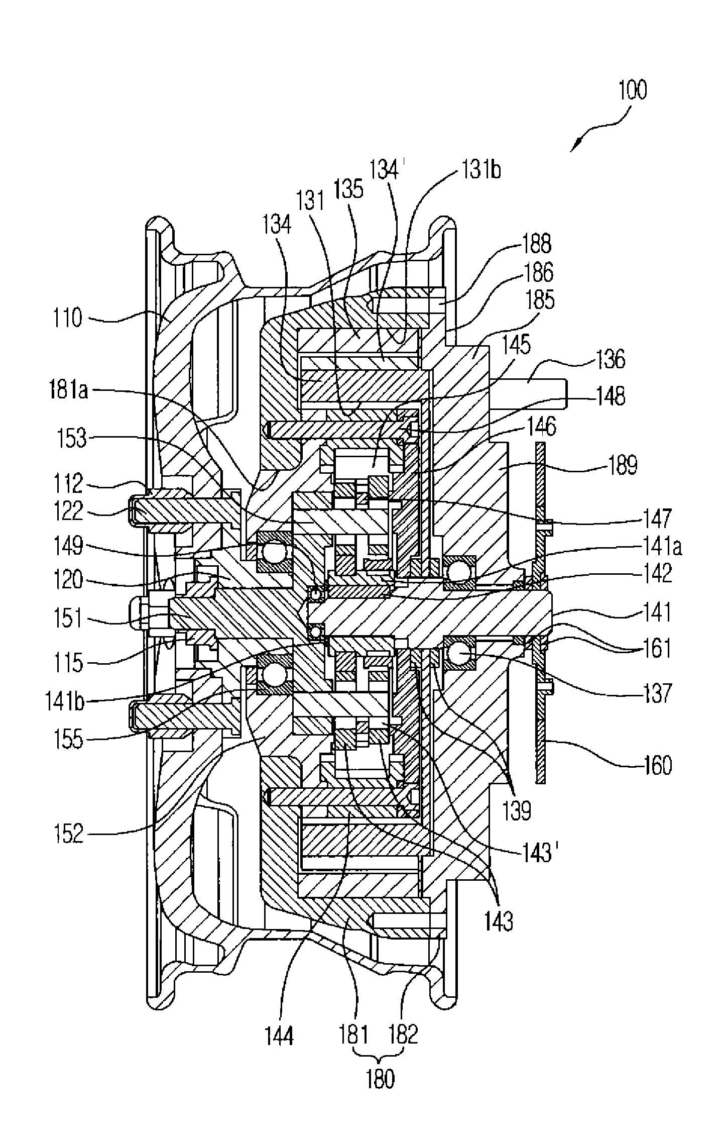
[0032]Embodiments of the present invention are directed to a mounting structure for an in-wheel motor system which allows the in-wheel motor system to be stably mounted to a vehicle through a...


PUM


Abstract

A mounting structure for an in-wheel motor system is provided. The mounting structure includes the in-wheel motor system installed in a wheel of the vehicle, and a torsion beam axle (TBA) assembly to fix the in-wheel motor system to a vehicle body, wherein a rear portion of a motor housing includes a step portion formed in a stepped manner to have a decreased diameter, and a ring-shaped fastening face vertically arranged from the step portion, and the TBA assembly includes a trailing arm provided with a through hole to surround the step portion of the motor housing, a mount integrated with the trailing arm to fix the trailing arm to a vehicle body, and a plurality of fastening bolts to fix the motor housing to the trailing arm, wherein, when the step portion is fitted and coupled into the through hole, the fastening face closely contacts the trailing arm.

Description

CROSS-REFERENCE TO RELATED APPLICATION(S)[0001]This application claims the benefit of Korean Patent Application No. 2012-0002312, filed on Jan. 9, 2012 in the Korean Intellectual Property Office, the disclosure of which is incorporated herein by reference.BACKGROUND[0002]1. Field[0003]Embodiments of the present invention relate to a mounting structure for an in-wheel motor system which allows the in-wheel motor system to be stably installed in a wheel of a vehicle and may increase efficiency of mounting and detaching of the in-wheel motor system.[0004]2. Description of the Related Art[0005]In general, an in-wheel motor, which is a technology applied to an electric motor using electricity as its power source, allows power to be directly transmitted from the motor disposed inside a rim of a wheel to the wheel, unlike transmission of power to the wheel through an engine, a transmission and a drive shaft to rotate the wheel in a gasoline-powered or diesel-powered vehicle.[0006]Such an i...

Claims


Application Information

Patent Timeline
Patent Type & Authority Patents(United States)
IPC IPC(8): B60K7/00B60K1/00
CPCB60K17/046B60K2007/0092B60G3/00B60K7/00B60K7/0007B60K2007/0038B60G2204/182B60K1/02
Inventor LEE, CHUNG, SEONG
Owner HL MANDO CORP
Why Eureka
Try Eureka