Temperature sensor

a technology of temperature sensor and sheath pin, which is applied in the field of temperature sensor, can solve the problems of cracking or breaking of welds or sheath pins, and achieve the effects of reducing acceleration, preventing the amplitude of inner members, and suppressing vibration

Active Publication Date: 2014-10-21
DENSO CORP
View PDF27 Cites 224 Cited by
  • Summary
  • Abstract
  • Description
  • Claims
  • Application Information

AI Technical Summary

Benefits of technology

[0021]In the above temperature sensor, the outer member has the clearance portion on the extending portion. The clearance portion has the air gap between itself and the inner member. This avoids the transmission of vibration of the internal combustion engine directly to the inner member from the fixed portion to suppress the vibration of the inner member or the sheath pin.
[0022]When the vibration is transmitted to the inner member, so that it has started to vibrate, the front interference portion provided in the extending portion of the outer member can suppress the amplitude of the inner member, thereby preventing the amplitude of the inner member from increasing to decrease the acceleration acting on the top end of the inner member.
[0023]Unlike the attenuation structure of the patent document 2, as described above, the front interference portion is so designed as to be disposed to have the maximum air gap of 0.2 mm or less between itself and the inner member in the radius direction to avoid the vibration of the inner member through the interference. This enables vibrational energy itself to be decreased which cannot be decreased by the attenuation of the vibration through a damper, as shown in the patent document 2. It is, therefore, possible not only to suppress the characteristic vibration of the inner member, but also the vibration of the temperature sensitive device having a resonance point within a frequency band higher than that of the inner member.
[0024]Further, even when the inner member starts to resonate with the outer member at its characteristic frequency, the front interference portion works to interfere with the inner member to suppress the resonance.
[0025]When the characteristic frequencies of the inner member and the outer member are different, they interfere with each other to suppress the vibration of the inner member.
[0026]As a result, the acceleration acting on the temperature sensitive device lying on the front end side of the inner member is decreased to decrease the stress exerted on the temperature sensitive device. This avoids the breakage of the temperature sensitive device or disconnection of electrodes of the temperature sensitive device, thereby providing the temperature sensor which is excellent in durability thereof.

Problems solved by technology

The excessive exertion of the stress on the joint between the sheath pin 3 and the rib 6 may result in cracks in or breakage of the weld or the sheath pin 3.

Method used


Image

  • Temperature sensor
  • Temperature sensor
  • Temperature sensor

Examples


embodiments

Embodiment 1

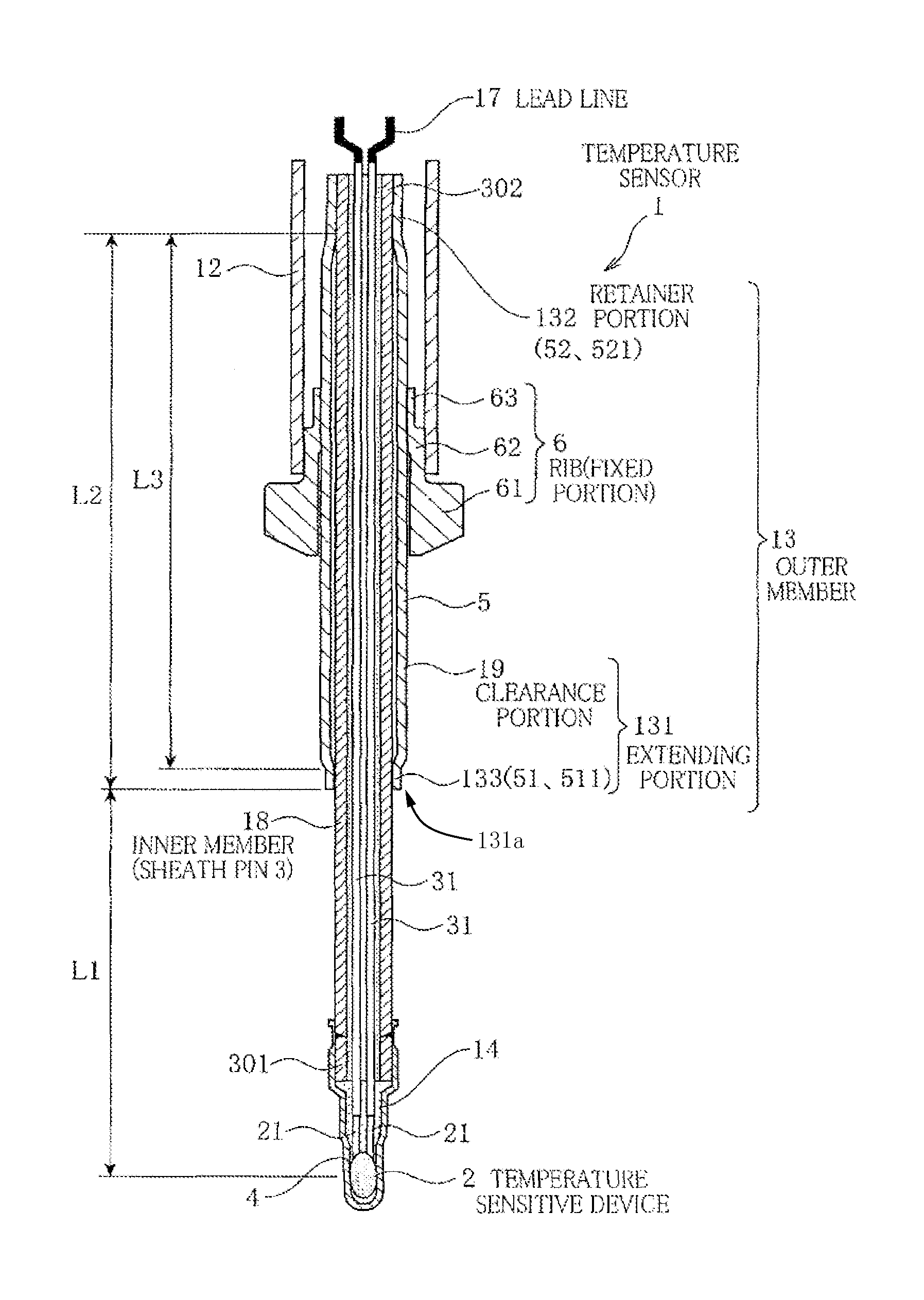
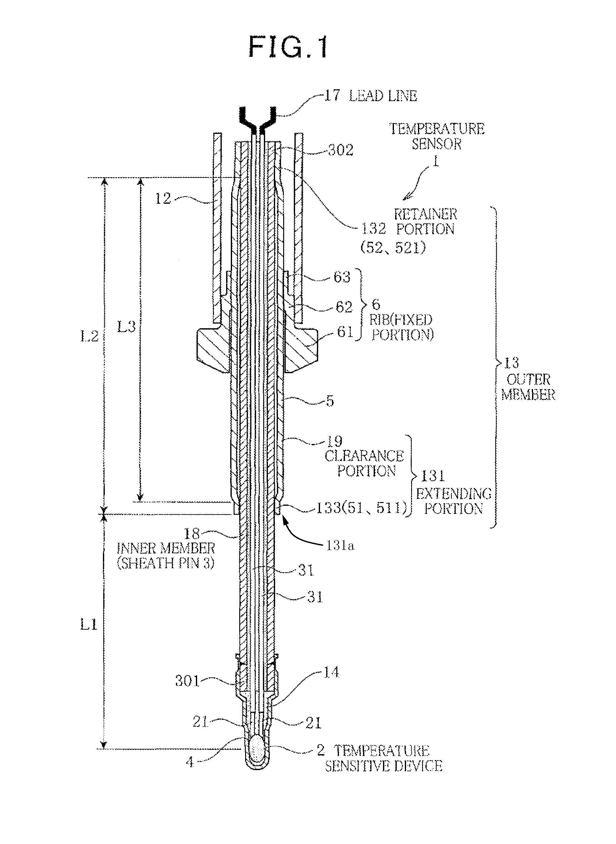
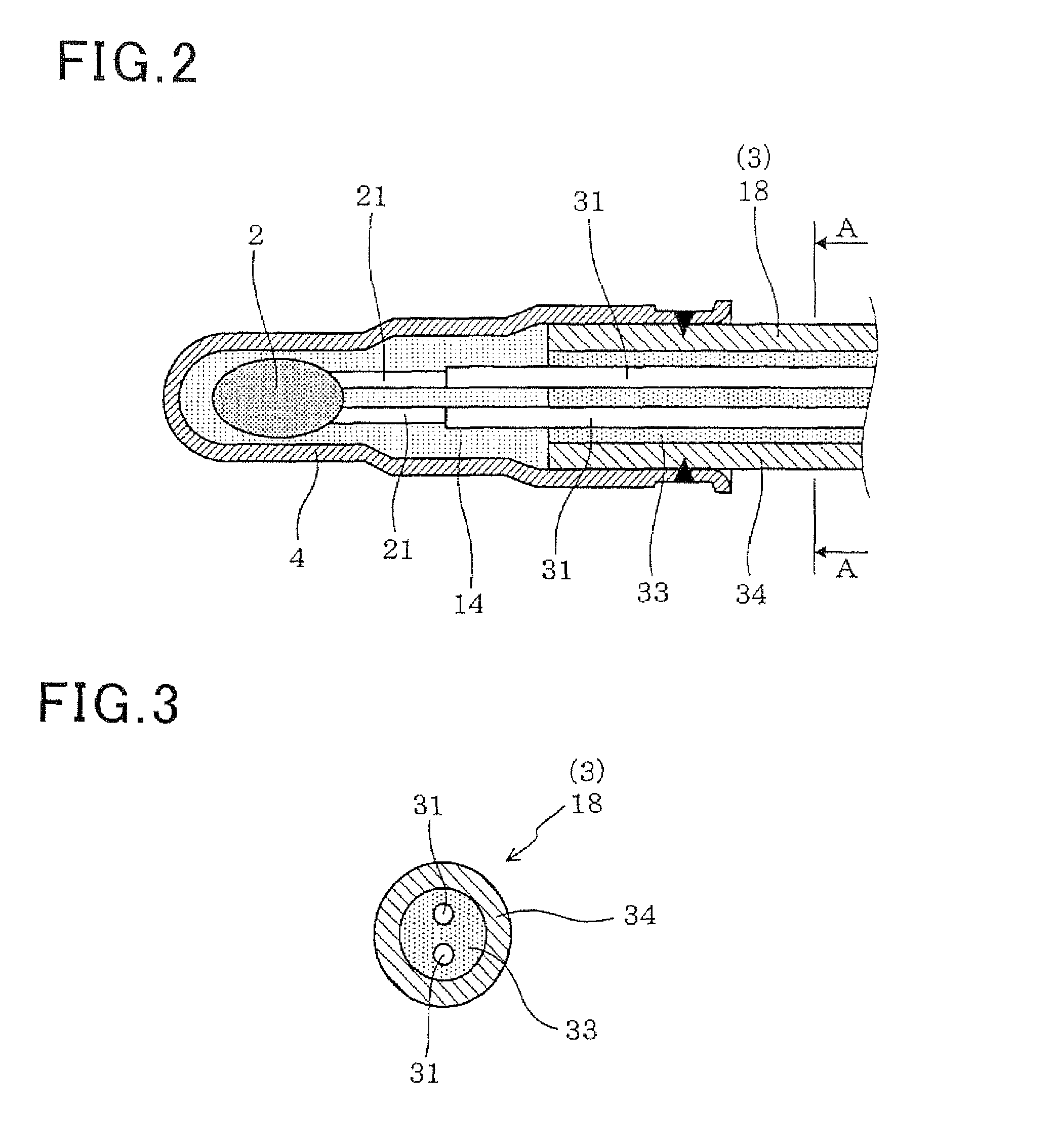
[0130]The temperature sensor according to an embodiment of the invention will be described below using FIGS. 1 to 4.

[0131]The temperature sensor 1 of this embodiment includes a temperature sensitive device 2 which is to be disposed in an exhaust pipe of an internal combustion engine, a pair of signal lines 31 which are connected at the top end side to the temperature sensitive device 2 and at the rear end side to lead wires 17 for connection with an external circuit, and an inner member 18 having a sheath pin 3 in which the signal lines 31 are disposed, and an outer member 13 disposed so as to surround at least a portion of an outer periphery of the inner member 18. The temperature sensor 1 has a metallic cover 4 disposed on a top end portion to cover the temperature sensitive device 2.

[0132]A guard tube 5 is disposed closer to the rear end side than the metallic cover 4 to cover the outer periphery of the sheath pin 3. The guard tube 5 has a rear end 52 thereof fixed to...

embodiment 2

[0177]This embodiment is to provide the temperature sensor 1 in which the air gap 11 (see FIG. 4) is not formed between the inner peripheral surface of the top end 51 of the guard tube 5 and the outer peripheral surface of the sheath pin 3.

[0178]Specifically, the temperature sensor 1 of this embodiment is so designed that the size S of the air gap 11 in FIG. 4 is zero (0).

[0179]In this embodiment, the top end 51 of the guard tube 5 may be placed in contacting abutment with the sheath pin 3. The top end 51 of the guard tube 5 is not fixed to the sheath pin 3 through, for example, welding. In this case, the parallel portion of the front interference portion 133 is in contact with the inner member 18 (i.e., the sheath pin 3), that is, placed in surface contact therewith when the size S of the air gap 11 is almost zero (0).

[0180]Other arrangements are identical with those in the first embodiment. The same effects as in the first embodiment are provided.

embodiment 3

[0215]This embodiment is an embodiment of the temperature sensor 1 in which the temperature sensitive device 2 is hermetically sealed by glass.

[0216]Other arrangements are identical with those in the first embodiment.

[0217]In this embodiment, it is possible to ensure the temperature measurement when the temperature sensor 1 is used in hot environmental conditions where a maximum temperature is 1000° C.

[0218]Specifically, in the above hot environment, the oxidation of the metal head cover 4 surrounding the temperature sensitive device 2 is accelerated, which result in a drop in concentration of oxygen within the metal head cover 4. This may cause the oxygen to leave the temperature sensitive device 2 to compensate for the drop in concentration of oxygen, so that the temperature sensitive device 2 is reduced, thus changing the performance thereof. The sealing of the temperature sensitive device 2 with the glass material minimizes this problem and ensures the accurate temperature measu...


PUM

PropertyMeasurementUnit
radiusaaaaaaaaaa
frequencyaaaaaaaaaa
sizeaaaaaaaaaa

Abstract

The temperature sensor 1 is equipped with a temperature sensitive device 2 to be disposed inside an exhaust pipe of an internal combustion engine, signal lines 31 connected at a top end side to the temperature sensitive device 2 and at a rear end side to leads for connection with an external circuit, an inner member 18 having a sheath pin 3 in which the signal lines 31 are disposed, and an outer member 13 disposed to cover at least a portion of an outer periphery of the inner member 18. The outer member 13 includes a fixed portion (rib 6) to be fixed to an upper wall of the exhaust pipe, a retainer portion 132 retaining the inner member 18, and an extending portion 131 formed closer to a top end side than the retainer portion 132. The extending portion 131 includes a clearance portion 19 disposed so as to have an air gap between itself and the inner member 18 and a front interference portion 133 disposed in a condition that a maximum air gap between the front interference portion 133 and the inner member 18 in a radius direction is 0.2 mm or less.

Description

[0001]This application is the U.S. national phase of International Application No. PCT / JP2008 / 051478 filed 31 Jan. 2008 which designated the U.S. and claims priority to Japanese Patent Application Nos. 2007-021834 filed 31 Jan. 2007, 2007-106162 filed 13 Apr. 2007 and 2008-017956 filed 29 Jan. 2008, the entire contents of each of which are hereby incorporated by reference.TECHNICAL FIELD[0002]The present invention relates to a temperature sensor which is to be installed in an exhaust system of an internal combustion engine.BACKGROUND ART[0003]There is a temperature sensor 9 which, as illustrated in FIG. 30, includes a temperature sensitive device 2, a sheath pin 3 in which a pair of signal lines 31 leading to the temperature sensitive device 2 are disposed, a metal cover 4 fit on the top to cover the temperature sensitive device 2, and a rib 6 retaining the outer periphery of the sheath pin 3 (Patent Document 1). In the temperature sensor 9, the sheath pin 3 and the rib 6 are welded...

Claims


Application Information

Patent Timeline
Patent Type & Authority Patents(United States)
IPC IPC(8): G01K1/08G01K1/14G01K13/02
CPCG01K2205/04G01K1/08G01K13/02G01K1/14
Inventor ABE, NOBUOHORI, TSUNENOBUKUROYANAGI, MASATOSHI
Owner DENSO CORP
Why Eureka
Try Eureka