Supercharge Your Innovation With Domain-Expert AI Agents!

Drive device

a technology of a drive device and a radial direction, which is applied in the direction of electrical equipment, supports/enclosements/casings, dynamo-electric machines, etc., can solve the problem of large radial direction size of the whole devi

Inactive Publication Date: 2014-10-21
DENSO CORP +1
View PDF37 Cites 9 Cited by
  • Summary
  • Abstract
  • Description
  • Claims
  • Application Information

AI Technical Summary

Benefits of technology

The invention aims to make the size of a drive device smaller in the radial direction.

Problems solved by technology

However, when the control circuit unit is arranged parallel with the shaft of the motor, a size of the whole device becomes large in a radial direction.

Method used


Image

  • Drive device
  • Drive device
  • Drive device

Examples


first embodiment

(First Embodiment)

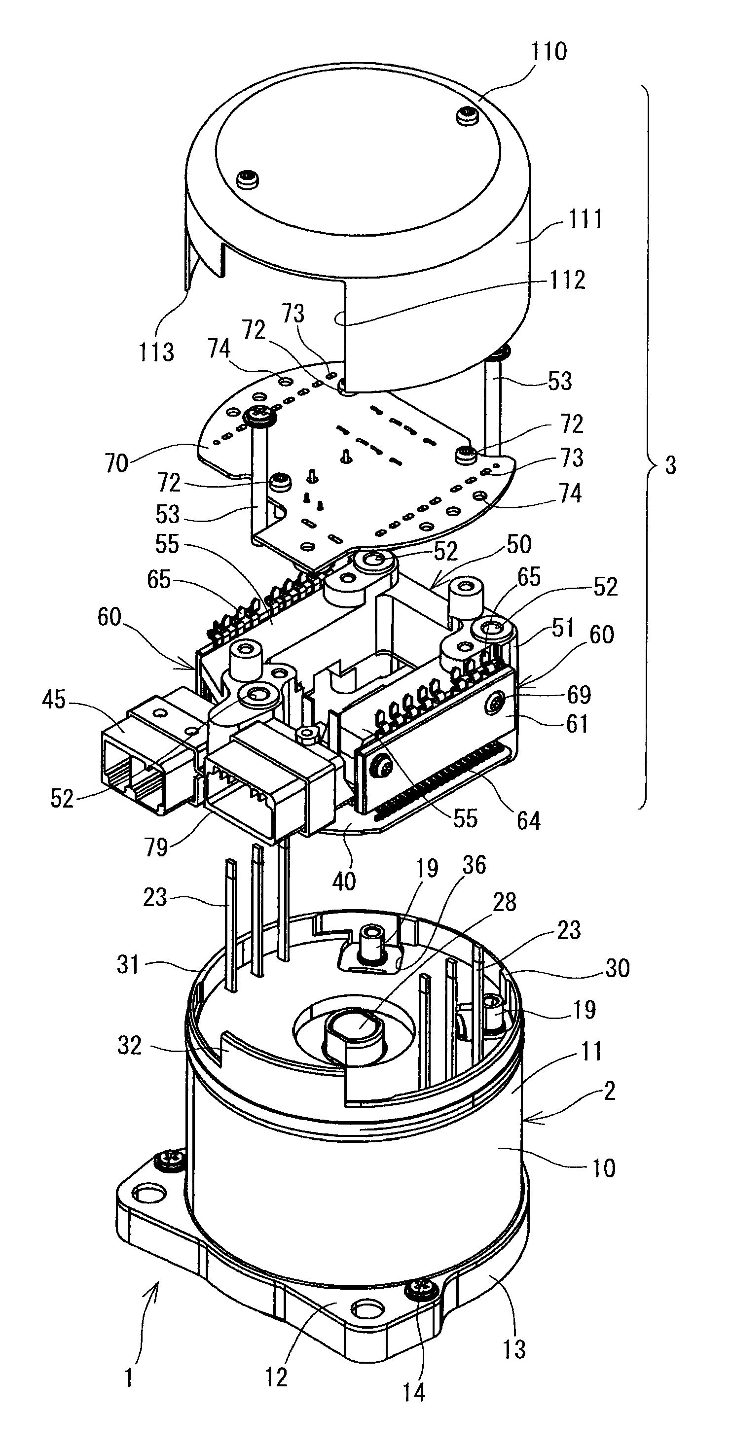
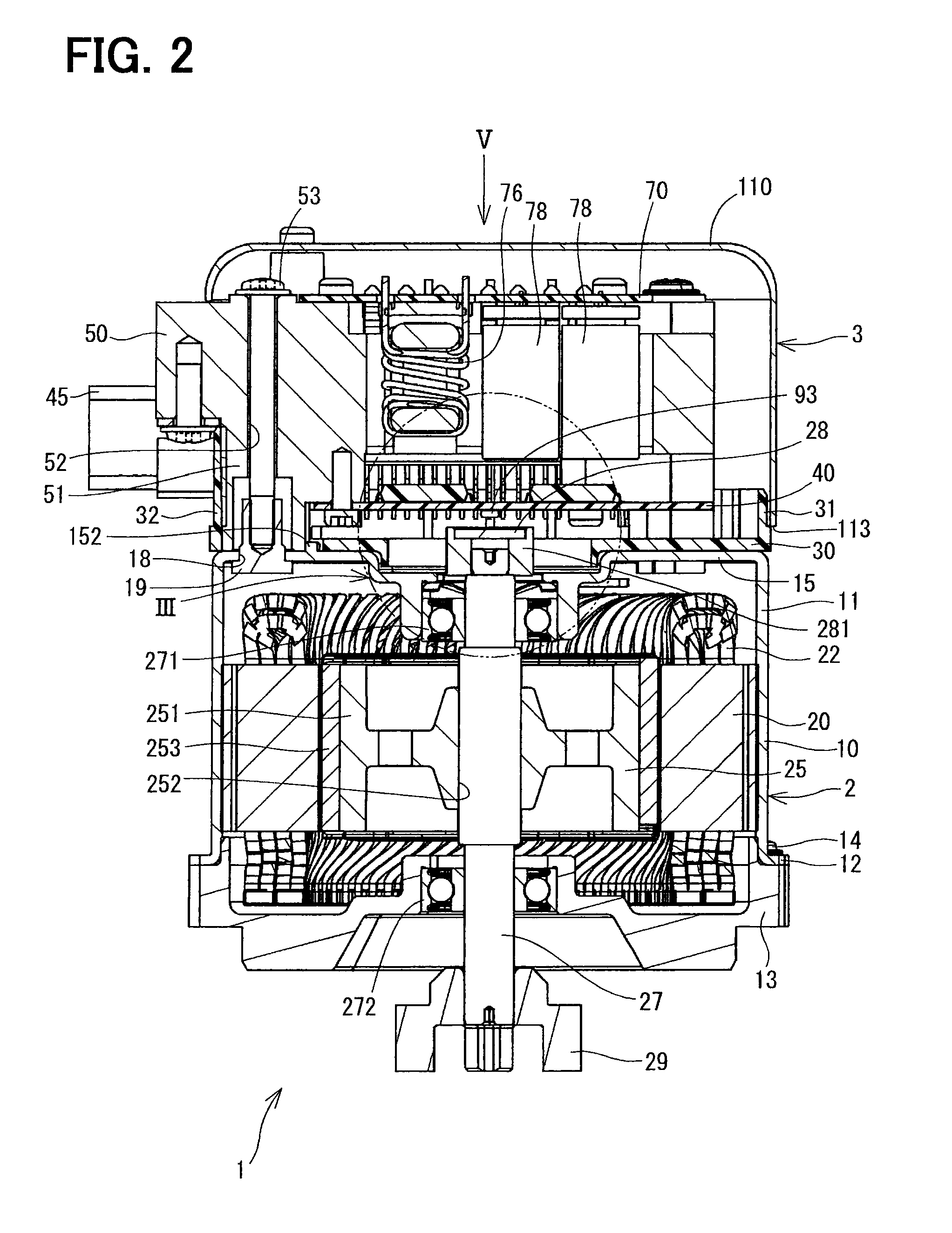
[0036]A drive device 1 according to a first embodiment will be described with reference to FIGS. 1-16. The drive device 1 is applied to an electric power-steering apparatus (hereinafter referred as EPS), and has a motor 2 and a control unit 3.

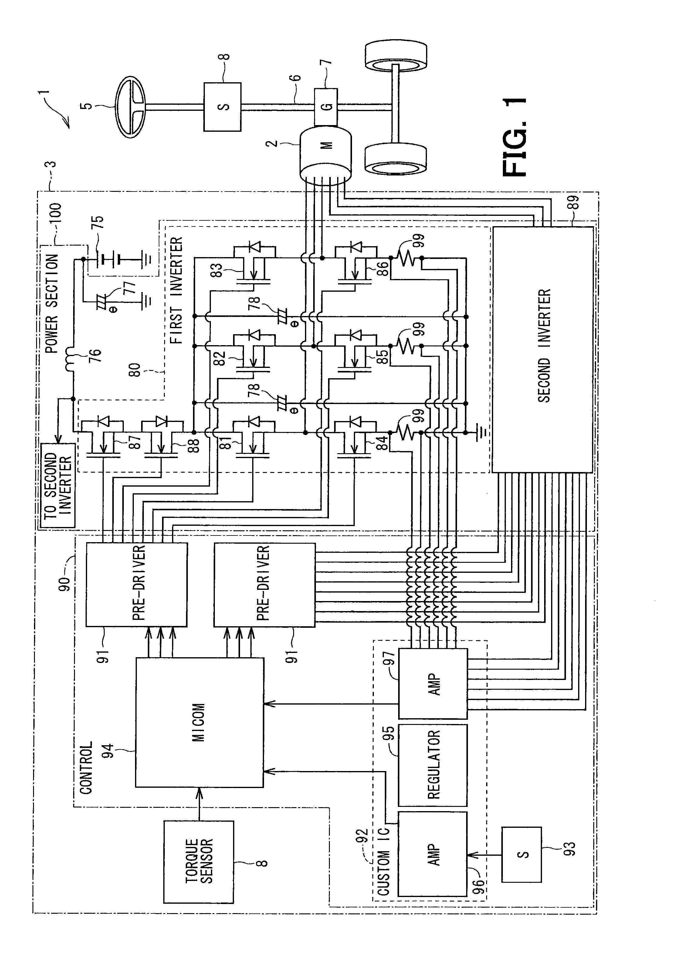
[0037]Referring to FIG. 1, electric construction of the EPS will be explained.

[0038]As shown in FIG. 1, a vehicle has a steering 5, a column shaft 6, and a gear 7. The drive device 1 produces rotation torque for the shaft 6 through the gear 7, so as to assist the steering 5.

[0039]Specifically, when a driver of the vehicle operates the steering 5, steering torque produced in the column shaft 6 by the operation is detected with a torque sensor 8. Further, speed information of the vehicle is acquired from a controller area network (CAN, not shown), so as to assist the steering 5. If such a mechanism is used, not only the assistance of the steering 5 but also automatic control of the steering 5 is possible such as lane keeping in ...

second embodiment

(Second Embodiment)

[0118]A second embodiment will be described with reference to FIGS. 17-24. FIGS. 17, 19-23 are views illustrating the whole of a drive device 200 according to the second embodiment. FIG. 18 is a cross-sectional view taken along a line XVIII-XVIII in FIG. 17. FIG. 24 is a cross-sectional view taken along a line XXIV-XXIV in FIG. 18.

[0119]The control device 3 of the drive device 200 has a cover 210 different from the cover 110 of the first embodiment.

[0120]The cover 210 has an end cover 211, a connector holder 220 and a holder 230. The cover 210 accommodates the control board 40, the heat sink 50 and the power module 60, and the power board 70 in the radial direction.

[0121]The end cover 211 is arranged at the end in the axis direction on the opposite side of the motor 2, and defines the outer shape opposite from the motor 2 in the axis direction. The end cover 211 has a based cylindrical shape made of metal material such as iron, and has a diameter approximately the...


PUM


Abstract

A drive device includes a motor, a control unit, a first fastener, and a second fastener. The control unit is arranged on a side of the motor in an axis direction of the motor. The first fastener is arranged in a wall part of a cylindrical motor case of the motor opposing to the control unit, on an inner side of a peripheral wall of the motor case in a radial direction. The second fastener is tightened with the first fastener so as to connect the motor and the control unit with each other.

Description

CROSS REFERENCE TO RELATED APPLICATION[0001]This application is based on Japanese Patent Application No. 2010-292290 filed on Dec. 28, 2010, and Japanese Patent Application No. 2011-74880 filed on Mar. 30, 2011, the disclosures of which are incorporated herein by reference in their entirety.BACKGROUND OF THE INVENTION[0002]1. Field of the Invention[0003]The present invention relates to a drive device.[0004]2. Description of Related Art[0005]A three-phase motor is known, and is driven to rotate when three-phase AC current is supplied from a power source. In a case where the power source is a DC power source having a predetermined voltage, a controller is necessary for switching a winding current, so as to supply the winding current having different phases to winding wire having plural (e.g., three) phases, respectively.[0006]JP-A-2003-204654 (US2003 / 0127921) describes a control circuit unit that is arranged parallel with a shaft of a motor and that is connected to a housing located o...

Claims


Application Information

Patent Timeline
Patent Type & Authority Patents(United States)
IPC IPC(8): H02K29/06H02K11/00H02K5/22H02K11/04
CPCH02K5/225H02K2211/03H02K11/0073H02K11/33
Inventor YAMASAKI, MASASHIIMAI, HIROSHI
Owner DENSO CORP
Features
  • R&D
  • Intellectual Property
  • Life Sciences
  • Materials
  • Tech Scout
  • Unparalleled Data Quality
  • Higher Quality Content
  • 60% Fewer Hallucinations
Learn More