
Video transmitting method and system with image quality adjusting function

a video and video transmission technology, applied in the field of video transmission methods and systems, can solve the problems of poor image quality, user satisfaction, and inability of the receiving terminal to play received videos smoothly in real-time, and achieve the effects of reducing the required transmission bandwidth, enhancing the image quality of the transmitted video stream, and reducing the amount of transmission bandwidth

Active Publication Date: 2014-10-21
CHICONY ELECTRONICS
View PDF6 Cites 2 Cited by
  • Summary
  • Abstract
  • Description
  • Claims
  • Application Information

AI Technical Summary

Benefits of technology

[0009]The present invention can achieve many advantages. A determination may be made as to whether the number of frames is sufficient according to the received number of frames of the transmitted video stream received by the receiving terminal in a preset period, and the image quality of the transmitted video stream can be dynamically adjusted according to the result thereof. When the received number of frames is determined to be insufficient, the image quality of the transmitted video stream can be reduced to decrease the required transmission bandwidth. Hence, the receiving terminal can receive the video stream normally, which leads to smooth real-time playing of the video stream. When the received number of frames is determined to be sufficient, the image quality of the transmitted video stream can be enhanced, which can provide users of the receiving terminal a better watching experience. In addition, image quality adjustment may be realized without having to ascertain the available bandwidth for transmission, such that better image quality can be provided to users without causing delay during playing of the video stream in real-time.

Problems solved by technology

In other words, if there is insufficient bandwidth for transmission, a receiving terminal cannot play received videos smoothly in real-time.
If the image quality of a video is reduced to enable smooth playing, users may not be satisfied.
Even when there is sufficient bandwidth for transmission, if compression parameters of the videos are not adjusted appropriately, the number of frames received by receiving terminals may be low to thereby result in poor image quality.

Method used


Image

  • Video transmitting method and system with image quality adjusting function
  • Video transmitting method and system with image quality adjusting function
  • Video transmitting method and system with image quality adjusting function

Examples


Embodiment Construction

[0019]Reference will now be made in detail to the present embodiments of the invention, examples of which are illustrated in the accompanying drawings. Wherever possible, the same reference numbers are used in the drawings and the description to refer to the same or like parts.

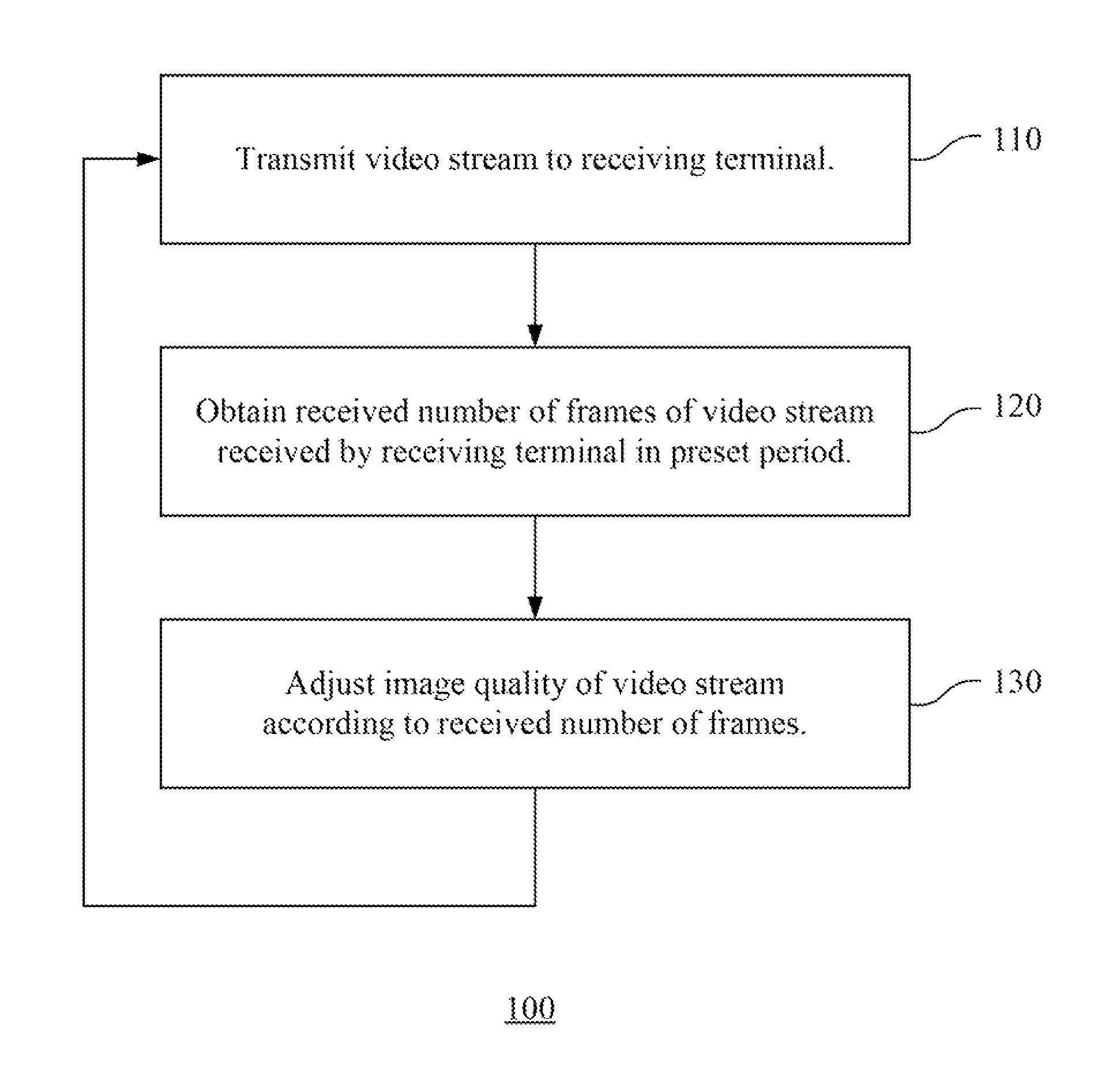
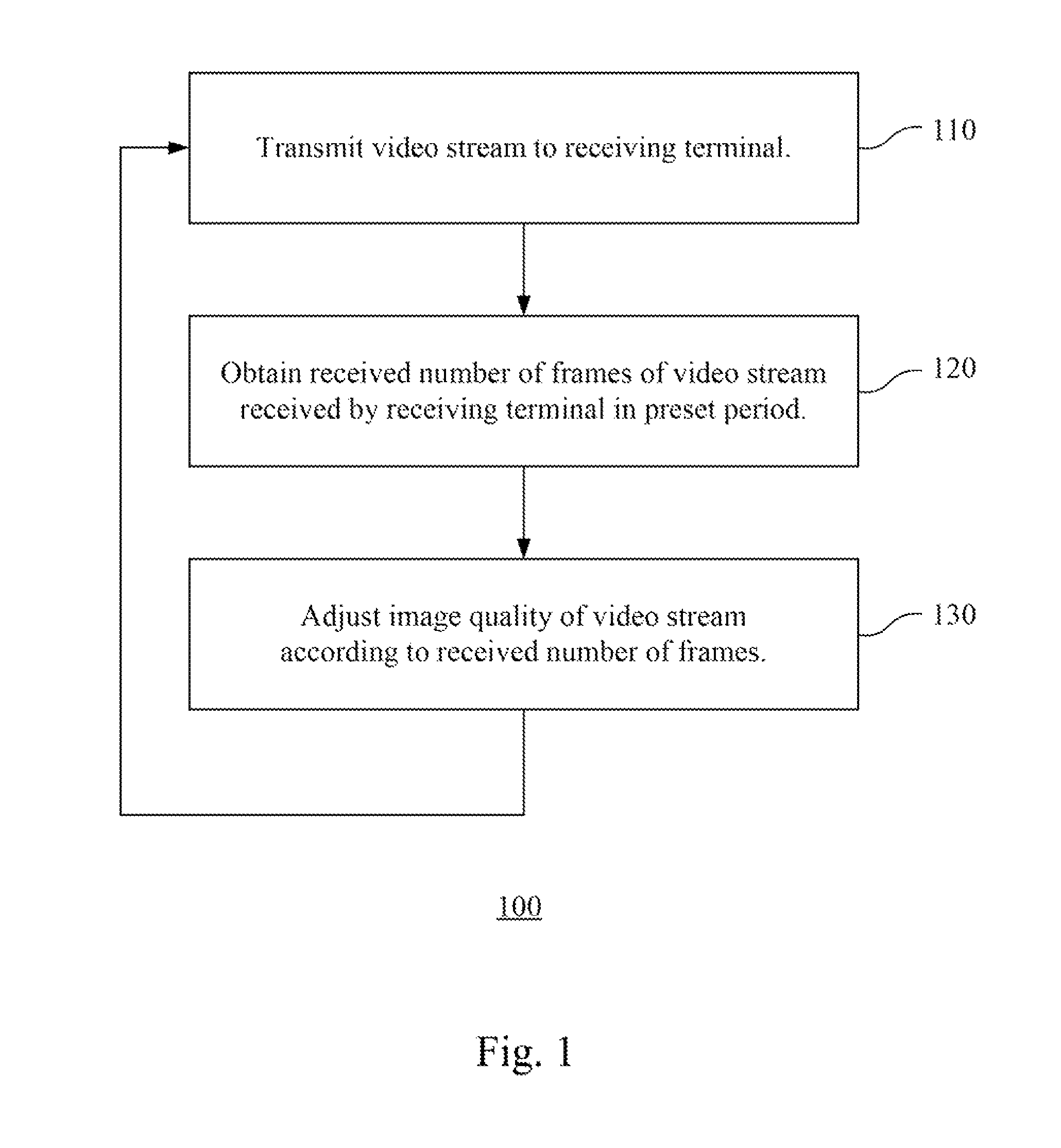
[0020]Referring to FIG. 1, a flow diagram will be described that illustrates a video transmitting method with an image quality adjusting function according to one embodiment of this invention. In the video transmitting method, the image quality of a transmitted video stream is adjusted according to the number of frames received by a receiving terminal in a preset period. The video transmitting method may take the form of a computer program product stored on a computer-readable storage medium having computer-readable instructions embodied in the medium. Any suitable storage medium may be used including non-volatile memory such as read only memory (ROM), programmable read only memory (PROM), erasable programmabl...


PUM


Abstract

A video transmitting method with an image quality adjusting function is provided. In the method, a video stream is transmitted to a receiving terminal. A received number of frames of the video stream received by the receiving terminal in a preset period is obtained. An image quality of the video stream is adjusted according to the received number of frames.

Description

RELATED APPLICATIONS[0001]This application claims priority to Taiwan Application Serial Number 100120400, filed Jun. 10, 2011, which is herein incorporated by reference.BACKGROUND[0002]1. Technical Field[0003]The present invention relates to a video transmitting method and system. More particularly, the present invention relates to a video transmitting method and system with an image quality adjusting function.[0004]2. Description of Related Art[0005]Websites for sharing videos are becoming more and more popular in recent times, and it is becoming a trend to upload and share filmed videos on the Internet. As image technology develops, videos with better quality can be uploaded and shared with others, and users tend to prefer watching videos with better image quality.[0006]Videos with better image quality often have large data sizes. Hence, more network bandwidth is required to transmit videos with higher image quality. In other words, if there is insufficient bandwidth for transmiss...

Claims


Application Information

Patent Timeline
Patent Type & Authority Patents(United States)
IPC IPC(8): H04N21/2343H04N7/12H04N21/238H04N7/173H04N21/239H04N21/24H04N21/442
CPCH04N21/23805H04N21/234381H04N21/2343H04N21/234363
Inventor HUANG, WEI-CHENGTSAI, MEI-YICHIEN, HSUAN-CHE
Owner CHICONY ELECTRONICS
Learn More