Gas piston control system for a firearm

a technology of control system and gas piston, which is applied in the field of gas piston control system for firearms, can solve the problems of shortening the life of the firearm, inability to quickly disassemble and clean, and increasing wear and tear, and achieves the effects of simple training users to operate, increased accuracy of the firearm, and elegant and simple methods of operation

Active Publication Date: 2014-10-28
RUCK MICHAEL ALAN +3
View PDF50 Cites 30 Cited by
  • Summary
  • Abstract
  • Description
  • Claims
  • Application Information

AI Technical Summary

Benefits of technology

[0006]An object of the present invention is to integrate an improved gas piston operating system into a firearm that increases accuracy of the firearm while retaining an elegant and simple method of operation. Another object of the present invention is to provide an improved gas piston operating system that is simple to train users to operate. Another object of the present invention is to provide an improved gas piston operating system that extends the life expectancy of high-wear components. Another object of the present invention is to provide an improved gas piston operating system that has the ability to compensate for various ammunition types and for the use of various suppressors.

Problems solved by technology

However, when firing rounds that develop high pressure levels, excessive energy is transmitted to the action which tends to increase wear and tear and shorten the life of the firearm.
Current methods of compensating for the varying pressure suffer from one or more of the following deficiencies: inability to adjust for a wide range of ammunition, inability to quickly disassemble and clean the mechanism such as might be necessary in the field, require the release of light, heat and sound which may render the weapon unsuitable for certain uses and inefficiencies render the method unsuitable for use with certain types of ammunition, such as subsonic rounds.

Method used


Image

  • Gas piston control system for a firearm
  • Gas piston control system for a firearm
  • Gas piston control system for a firearm

Examples


Embodiment Construction

[0022]In the following description of the preferred embodiments, reference is made to the accompanying drawings which show by way of illustration specific embodiments in which the invention may be practiced. Wherever possible, the same reference numbers will be used throughout the drawings to refer to the same or like parts. It is to be understood that other embodiments may be utilized and structural and functional changes may be made without departing from the scope of the present invention.

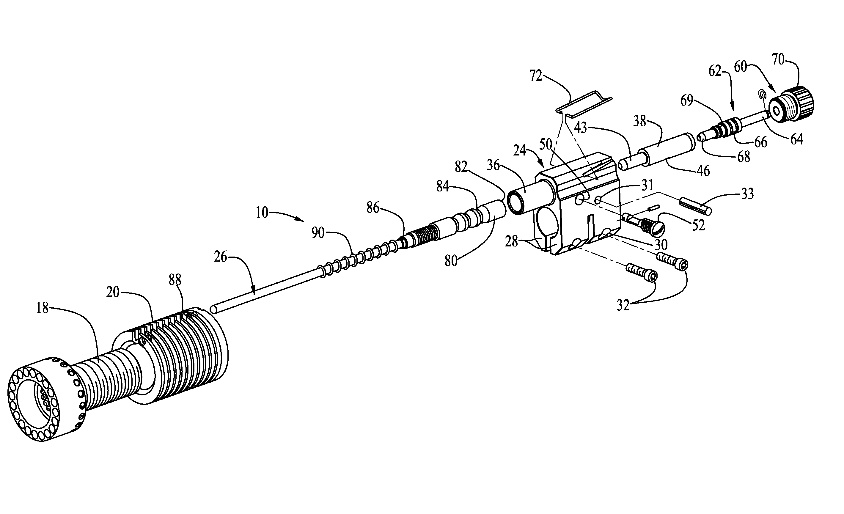
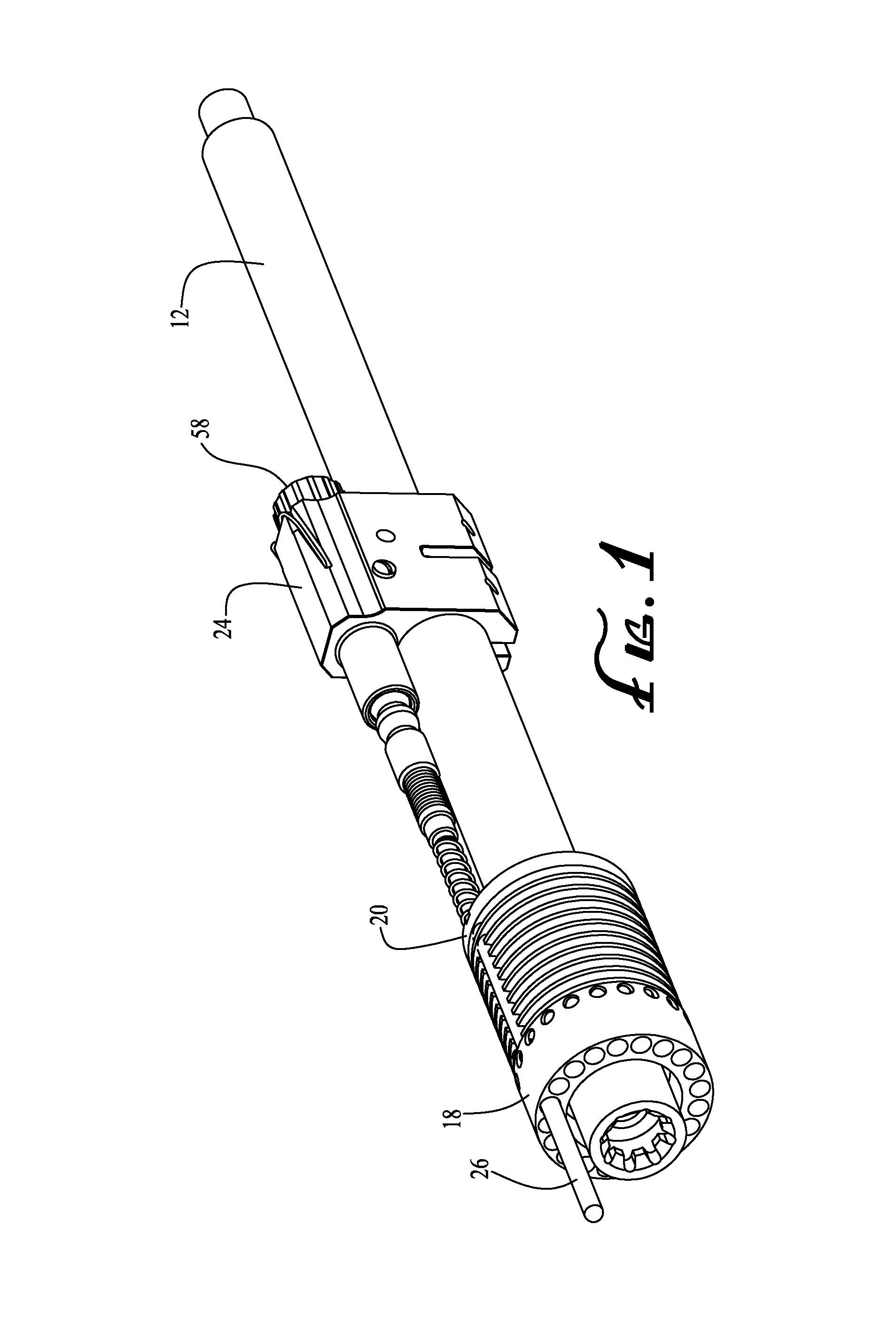
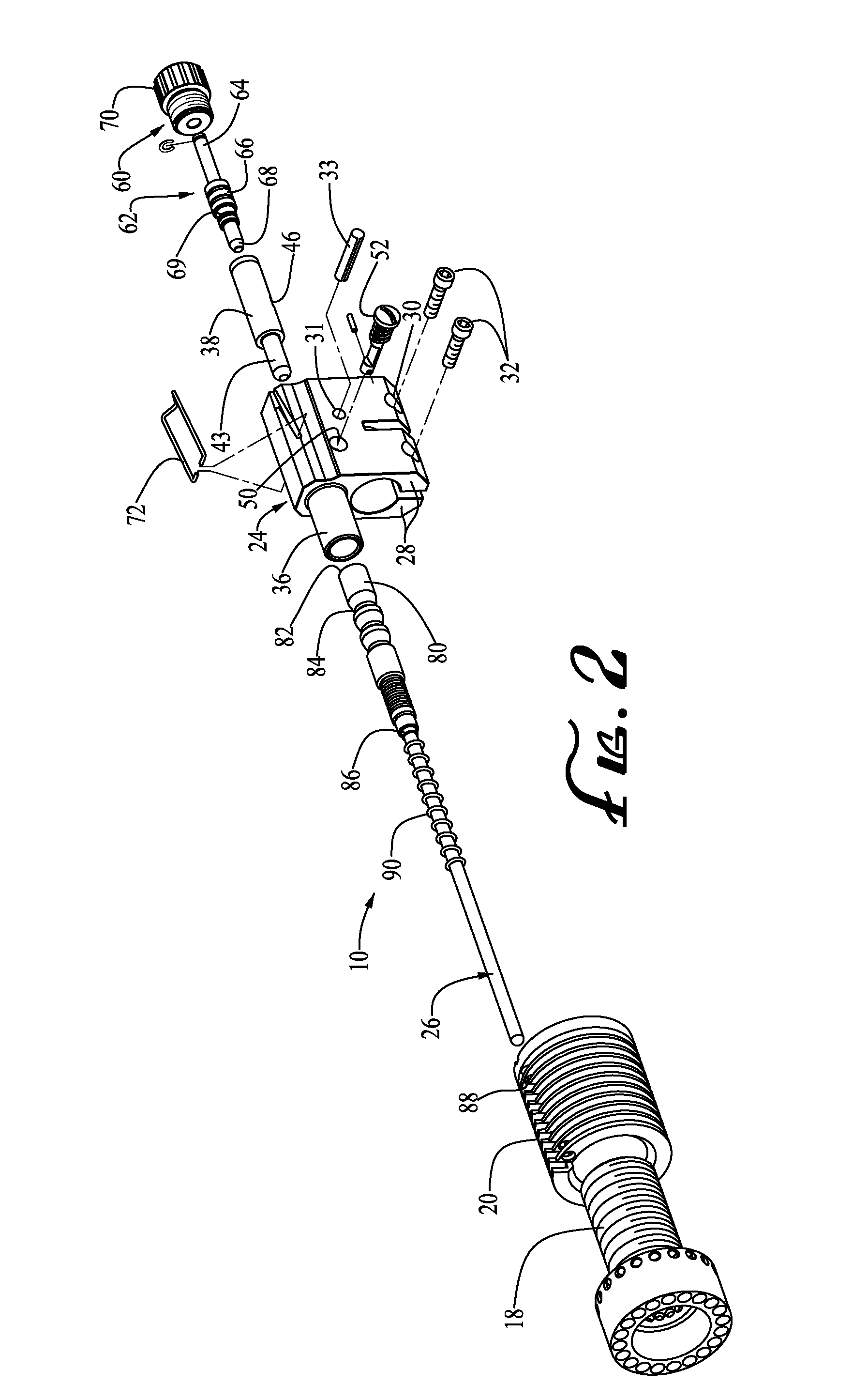
[0023]FIGS. 1 to 6 show a gas piston control system 10 for a firearm according to an embodiment of the present invention. The firearm has a cylindrical barrel 12 having a bore 14. The barrel 12 is mounted to an upper receiver of the firearm using a barrel nut 18. A heat sink20 is mounted on the barrel nut 18 at a proximal end of the barrel 12. A chamber in the upper receiver adjacent the proximal end of the barrel 12 is configured to receive a cartridge provided with a projectile. When the cartr...


PUM


Abstract

A gas system for a firearm having a gas block coupled to a barrel with a gas capture port in communication with a barrel gas port. A sleeve removeably mounted inside the gas block has: a gas conduit; a seat near the gas conduit; a projection; and a rod conduit communicating gas through the projection. A rod movably mounted in the gas block has a cup fitting over the projection.A valve has a knob coupleable to the gas block and a plug moveable within the pressure sleeve with a plunger engageable with the seat to adjust gas flow through the gas conduit to the rod conduit. Gas discharged from a fired cartridge flows against the cup to drive the rod to reload the firearm. The plug is moveable by the knob to a plurality of positions to alter the gas conveyed to the rod.

Description

CROSS-REFERENCE TO RELATED APPLICATION(S)[0001]This application claims priority of U.S. Provisional Patent Application No. 61 / 633,639 filed on Feb. 14, 2012, entitled RIFLE LOWER AND UPPER RECEIVER AND MONOLITHIC HANDGUARD RAIL SYSTEM AND GAS PISTON SYSTEM AND IMPROVEMENTS, the entire contents of which are hereby incorporated herein by reference.BACKGROUND OF THE INVENTION[0002]The present invention relates to firearms and, more particularly, to gas recoil automatic and semiautomatic firearms and to improvements in the gas systems thereof.[0003]In firearms of the gas operated type in which propellant gases are tapped from the barrel and employed to drive a piston which actuates the gun action, it is often desirable to have some means of regulating the energy transmitted to the piston. This is especially desirable in firearms that are adapted to fire a variety of types of ammunition, each developing widely varying pressure characteristics in the barrel.[0004]If no control device is p...

Claims


Application Information

Patent Timeline
Patent Type & Authority Patents(United States)
IPC IPC(8): F41A5/28
CPCF41A5/28
Inventor RUCK, MICHAEL ALANANDERSON, ROBERTANDERSON, ERIK CHRISTOPHERRUCK, MICHAEL ARTHUR
Owner RUCK MICHAEL ALAN
Why Eureka
Try Eureka