Light mixing module

a technology of light mixing module and light mixing, which is applied in the direction of instruments, lighting and heating apparatus, semiconductor devices of light sources, etc., can solve the problems of low luminous efficiency, excessive fabrication cost, and white light production

Active Publication Date: 2014-10-28
IND TECH RES INST
View PDF19 Cites 31 Cited by
  • Summary
  • Abstract
  • Description
  • Claims
  • Application Information

AI Technical Summary

Problems solved by technology

However, the current LED capable of producing the white light is disadvantageous in excessively high fabrication cost and low luminous efficiency, which hold back the mass production and application promotion of the same.

Method used


Image

  • Light mixing module
  • Light mixing module
  • Light mixing module

Examples


Embodiment Construction

[0037]In the following detailed description, for purposes of explanation, numerous specific details are set forth in order to provide a thorough understanding of the disclosed embodiments. It will be apparent, however, that one or more embodiments may be practiced without these specific details. In other instances, well-known structures and devices are schematically shown in order to simplify the drawing.

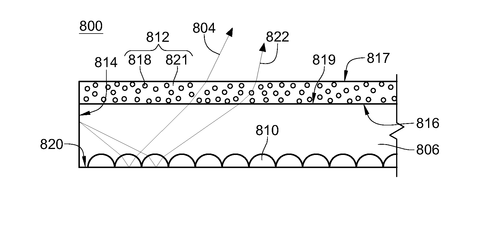
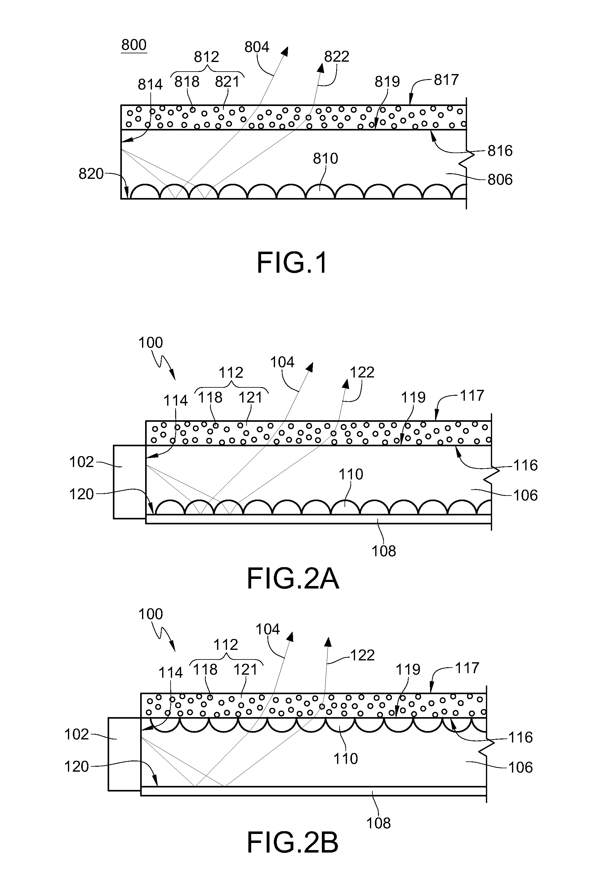
[0038]FIG. 1 is a schematic view of the structure of a light mixing module according to one embodiment. The light mixing module 800 is applied for receiving a first light 804 which has a first wavelength λ1. The light mixing module 800 includes a matrix 806, a plurality of micro-structures 810, and a fluorescent film 812. The matrix 806 includes an incidence surface 814, an emission surface 816, and a reflective surface 820. The incidence surface 814 is adjacent to the emission surface 816. The emission surface 816 and the reflective surface 820 are opposite to each other. The fluor...


PUM

PropertyMeasurementUnit
thicknessaaaaaaaaaa
diameteraaaaaaaaaa
thicknessaaaaaaaaaa

Abstract

A mixing light module includes a matrix, a fluorescent film, and a plurality of micro-structures. The matrix includes an incidence surface, an emission surface and a reflective surface. The fluorescent film disposed on or above the emission surface has an upper surface and a lower surface and includes a plurality of fluorescent particles. The matrix receives a first light having a first wavelength, and the reflective surface reflects the first light to make the first light to be emitted from the emission surface. Since the plurality of fluorescent particles receives a part of the first light from the emission surface, the plurality of fluorescent particles is excited to emit a second light having a second wavelength. The second light and the first light are mixed into a predetermined light. The plurality of micro-structures is used to make the first light or the second light uniform.

Description

CROSS-REFERENCE TO RELATED APPLICATIONS[0001]This non-provisional application claims priority under 35 U.S.C. §119(a) on Patent Application No(s). 099147373 filed in Taiwan, R.O.C. on Dec. 31, 2010 and Patent Application No(s). 100140605 filed in Taiwan, R.O.C. on Nov. 7, 2011, the entire contents of which are hereby incorporated by reference.BACKGROUND[0002]1. Technical Field[0003]The technical field relates to a light mixing module.[0004]2. Related Art[0005]Currently, a light-emitting diode (LED) capable of producing a white light is mainly obtained in the following three methods. In the first method, an LED emitting a blue light is used to irradiate an yttrium aluminum garnet (YAG) to produce a yellow light complementary to the blue light. Then, the yellow light and the blue light complementary to each other are mixed by using the light scattering principle to obtain a white light. In the second method, a matrix made of zinc selenide (ZnSe) capable of emitting a yellow light is p...

Claims


Application Information

Patent Timeline
Patent Type & Authority Patents(United States)
IPC IPC(8): F21V8/00G02F1/1335F21Y105/00F21K99/00F21Y101/02F21V7/04F21V5/00F21V9/40
CPCF21K9/56G02B6/0036G02B6/005F21Y2101/02F21V5/002G02F1/133606F21Y2105/00F21K9/54G02F2001/133614G02F1/133602F21K9/62F21K9/64F21Y2115/10F21V5/10G02F1/133614
Inventor LIN, HUI-HSIUNGFU, CHIUN-LERNHUNG, HSIAO-WENYANG, WEN-HSUNLIAO, CHI-HUNGCHEN, WEN-JUNG
Owner IND TECH RES INST
Why Eureka
Try Eureka