Method for fabricating led light tube

a technology of led light tubes and manufacturing methods, which is applied in the direction of semiconductor devices for light sources, lighting and heating apparatus, solid-state devices, etc., can solve the problems of high manufacturing cost, large amount of waste of materials, and inability to reduce the overall manufacturing cost of led light tubes, so as to shorten the distance between adjacent pairs, shorten the manufacturing time, and reduce the cost of material expenses

Inactive Publication Date: 2014-10-28
GEM WELTRONICS TWN CORP
View PDF2 Cites 0 Cited by
  • Summary
  • Abstract
  • Description
  • Claims
  • Application Information

AI Technical Summary

Benefits of technology

[0010]One distinct feature of the present invention resides in that once the LED dies are disposed on the bottom surface of the recess in the heat dissipation base, the optical layer and the protection layer can be sequentially disposed over the LED dies, thereby finishing the production of manufacturing the LED light tube of the present invention. Under such a situation, several components of the prior are deleted, which are in fact not directly related to the LED light tube. There are several specifications for packing the LED light tube.
[0011]Another distinct feature of the present invention resides in that the LED dies coupled electrically via the conductive elements for various objective can shorten the distance between adjacent pair of the LED dies. Hence an appropriate adjustment can be conducted among the LED dies in order to achieve densely arrangement of the LED dies so that the LED light tubes thus produced can provide the outmost amount of brightness. At the same time, during the wire-bond operation, since the LED dies and the conducting elements can be kept at appropriate distance, since shorter wires are required for wire bond purpose, tangling among the wires can be avoided.
[0012]In accordance with the integrally formed concept, the heat dissipation base with the recess, the illumination unit and the bridging unit are integrally fabricated. The heat dissipation base is fabricated in such a manner to have different longitudinal lengths so as to form the light tubes of different specifications. Hence, the cost of material expense is greatly reduced and hence shortening the manufacture time.

Problems solved by technology

The preceding several processes and assembly process and several structure of the LED units and the printed circuit plate are in fact not directly related to the LED light tube so that an overall manufacturing cost thereof cannot be reduced, thereby wasting a relatively large amount of materials.
The manufacturing cost is therefore high and consequently results in long manufacturing time.

Method used


Image

  • Method for fabricating led light tube
  • Method for fabricating led light tube
  • Method for fabricating led light tube

Examples


Embodiment Construction

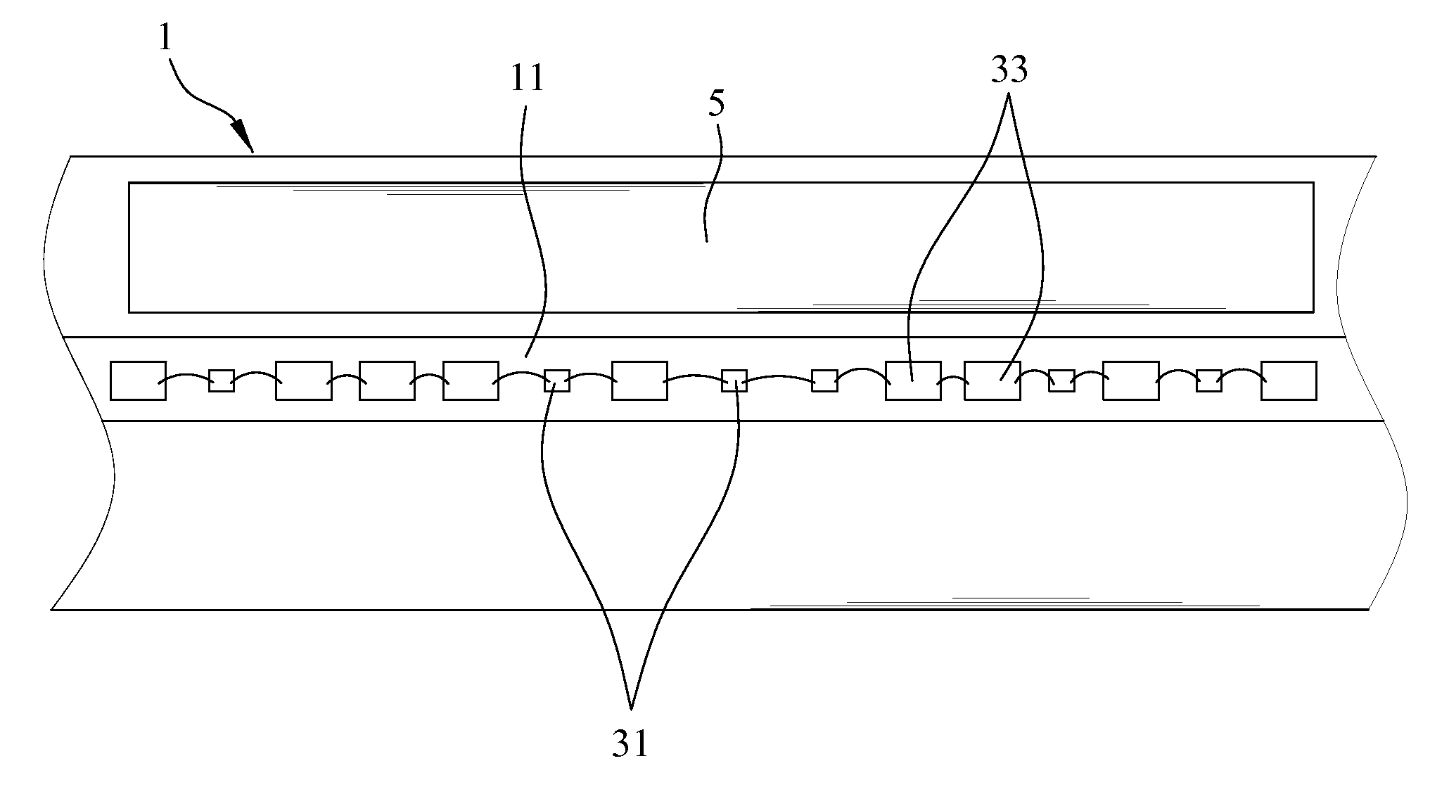
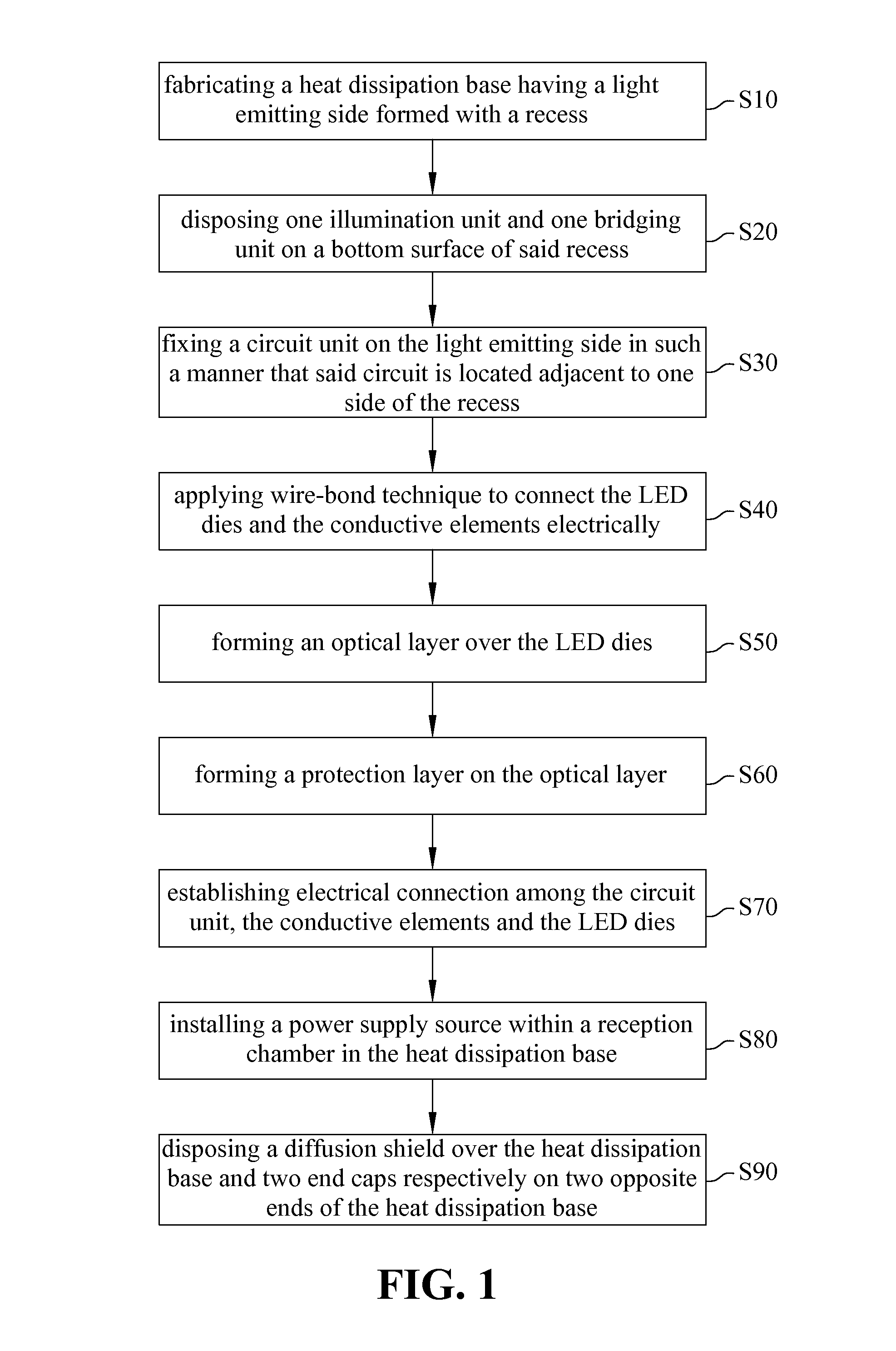
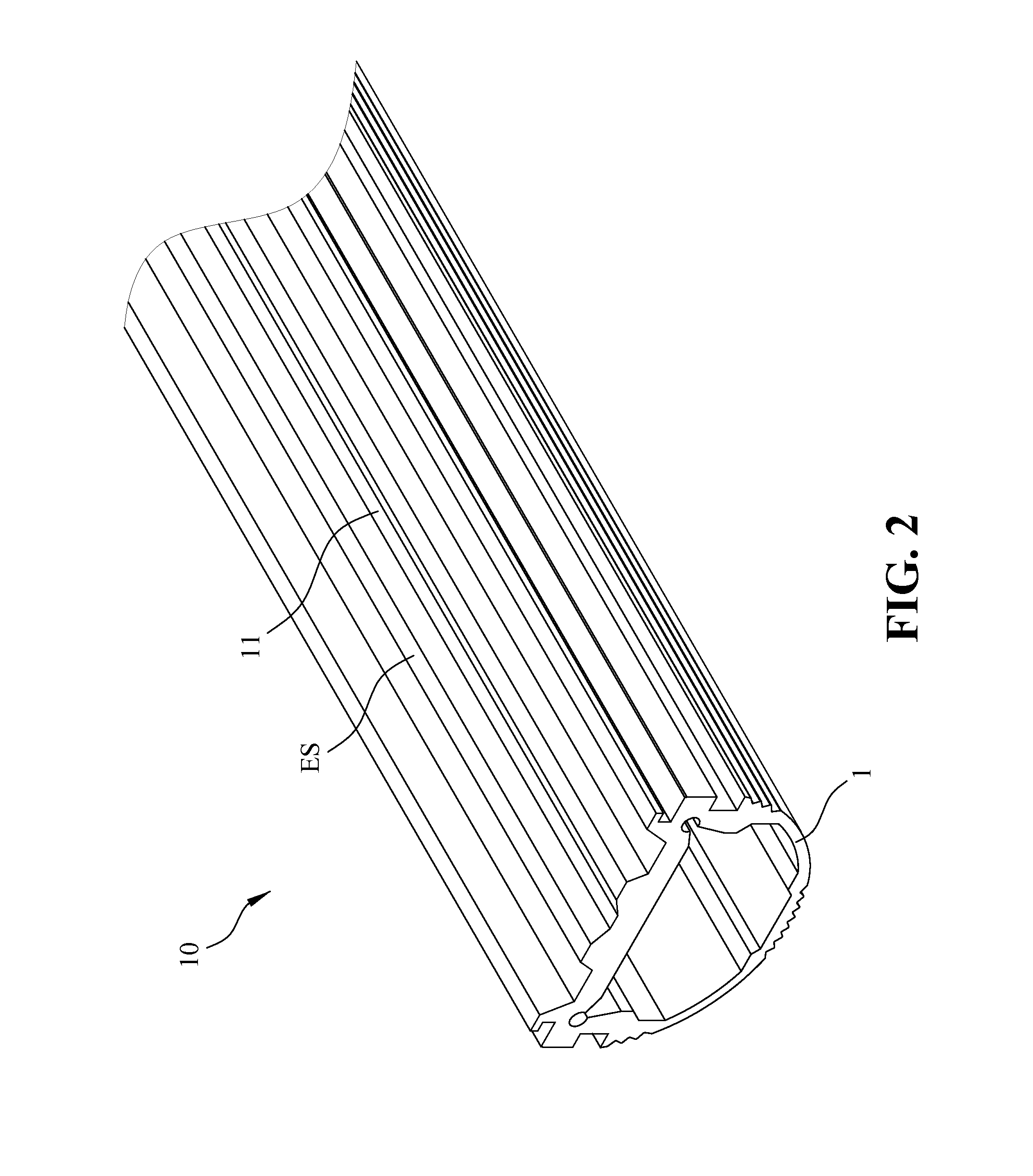
[0025]Referring FIGS. 1-2, FIG. 1 is a block diagram illustrating the steps in a method for fabricating an integrally formed light emitting diode (LED) light tube of the present invention; FIG. 2 shows a perspective view of a heat dissipation base employed in the method for fabricating the integrally formed LED light tube of the present invention. As shown in FIG. 1, according to the step S10; a heat dissipation base 1 is fabricated to have a light emitting side ES formed with a recess 11, the heat dissipation base 1 further has an interior portion defining a reception chamber therein, as best shown in FIG. 2.

[0026]Preferably, the recess 11 of the heat dissipation base 1 has a bottom surface and two lateral sides, each extending inclinedly from one end of the bottom surface such that the recess 11 is generally V-shaped.

[0027]In this embodiment, the heat dissipation base 1 is fabricated from aluminum or other conductive metals via extrusion method or die casting. Preferably, the bott...


PUM


Abstract

A method for fabricating an LED light tube includes: fabricating a heat dissipation base having a light emitting side with a recess and a reception chamber; disposing one illumination unit and one bridging unit on the recess, wherein the illumination unit and the bridging unit are constituted by LED dies and conductive elements, respectively; fixing a circuit unit on the light emitting side in such a manner that the circuit is located adjacent to the recess; applying wire-bond technique to connect the LED dies and the conductive elements electrically; forming an optical layer over the LED dies; forming a protection layer on the optical layer; establishing electrical connection among the circuit unit, the conductive elements and the LED dies; installing a power supply source within the reception chamber; and disposing a diffusion shield over the dissipation base and two end caps respectively on two ends of the dissipation base.

Description

BACKGROUND OF THE INVENTION[0001]1. Field of the Invention[0002]The present invention relates to a light emitting diode (LED) light tube, more particularly to a method for fabricating an integrally formed LED light tube provided with a bridging unit.[0003]2. The Prior Arts[0004]Owing to high efficiency, long lasting, small size, low energy consuming, swift in response, and mature advance in the modern electronics lately, a majority of traditional light bulbs or light tubes are gradually replaced with LED light tubes.[0005]A prior art LED light tube generally includes a light tube, a heat dissipation plate, a printed circuit board, a plurality of LED units and two conductive caps. The heat dissipation plate is mounted within the light tube while the printed circuit board is mounted on the heat dissipation plate. The LED units are connected electrically with the printed circuit board.[0006]During the assembly, the LED units are first of all soldered on the printed circuit board, after...

Claims


Application Information

Patent Timeline
Patent Type & Authority Patents(United States)
IPC IPC(8): H01L21/00H01L33/64H01L33/62
CPCH01L33/62H01L33/642F21K9/00F21K9/90F21K9/27H01L2224/48091H01L2924/00014
Inventor HWU, JON-FWUWU, YUNG-FULIU, KUI-CHIANG
Owner GEM WELTRONICS TWN CORP
Why Eureka
Try Eureka