
Power generating system using wasting energy from moving objects

a technology of moving objects and power generation systems, applied in the direction of machines/engines, vehicles, transportation and packaging, etc., can solve the problems of limited use of windmills, prior art does not teach utilizing mechanical energy of non-moving objects, and achieves high voltage of electricity

Active Publication Date: 2014-10-28
K TECH INC
View PDF81 Cites 40 Cited by
  • Summary
  • Abstract
  • Description
  • Claims
  • Application Information

AI Technical Summary

Benefits of technology

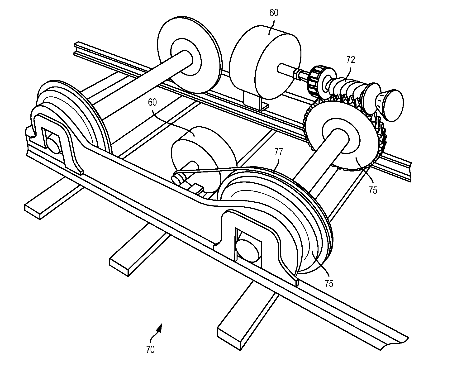
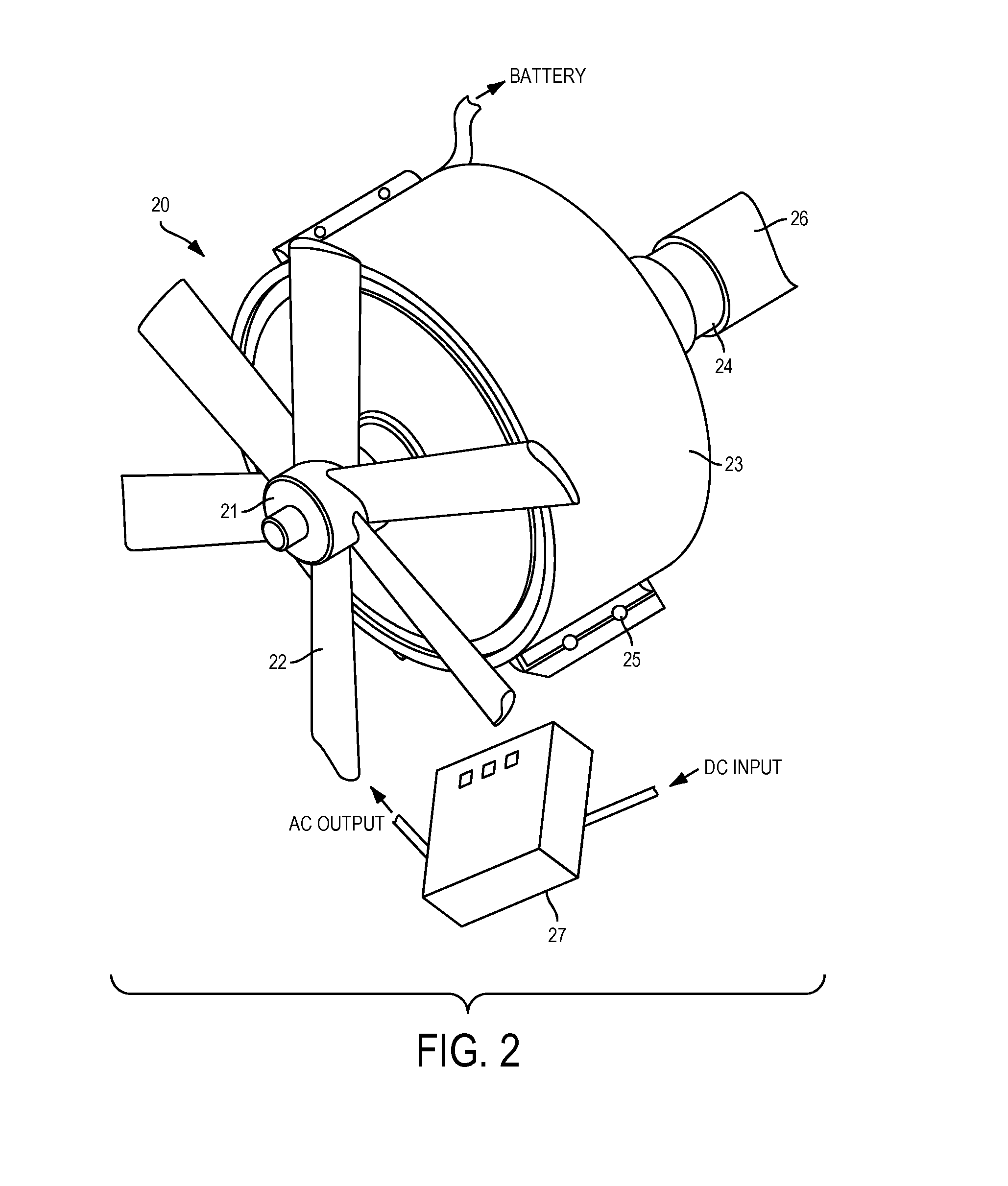
The present invention provides an air power generator system that can generate electricity by using the wind power of a moving object, such as an automobile, airplane, ship, or helicopter. The system includes a rotating shaft, a fan, and a power generator connected to the rotating shaft. The system can produce high voltage DC power when the moving object moves over 10 miles per hour. The generated power can be used to recharge batteries or operate devices in the moving object. The system can also include a CPU to generate alarms, control a DC / AC converter, or adjust the RPM of the rotating shaft. Overall, the invention provides a unique and effective way to generate power from moving objects.

Problems solved by technology

As such, the utility of the wind mills are limited, depend on natural wind, and are costly.
However, the prior art does not teach producing high amount of electricity by utilizing wasting mechanical energy of rotating wheels of moving objects such as automobiles, trains, airplanes, ships, helicopter and the like.
Further, the prior art does not teach utilizing wasting mechanical energy of non-moving objects such as machines and equipment used in many different industries and assembly plants.

Method used


Image

  • Power generating system using wasting energy from moving objects
  • Power generating system using wasting energy from moving objects
  • Power generating system using wasting energy from moving objects

Examples


Embodiment Construction

[0049]Reference will now be made in detail to embodiments, examples of which are illustrated in the accompanying drawings, wherein like reference numerals refer to the like elements throughout. In this regard, the present embodiments may have different forms and should not be construed as being limited to the descriptions set forth herein. Accordingly, the embodiments are merely described below, by referring to the figures, to explain aspects of the present description. Terms used herein are for descriptive purposes only and are not intended to limit the scope of the invention. The terms “comprises” and / or “comprising” are used to specify the presence of stated elements, steps, operations, and / or components, but do not preclude the presence or addition of one or more other elements, steps, operations, and / or components. The terms “first”, “second, and the like may be used to describe various elements, but do not limit the elements. Such terms are only used to classify one element fr...


PUM


Abstract

Provided is a power generating system that includes at least one power generator connected to a first rotating shaft having at least one of a first gear, a first pulley, a first crankshaft, or a first eccentric shaft, the first rotating shaft connected to a second rotating shaft of at least one of a moving object or a rotating machine producing wasting mechanical energy and having at least one rotating wheel, the second rotating shaft having a second gear, a second pulley, a second crankshaft, or a second eccentric shaft.

Description

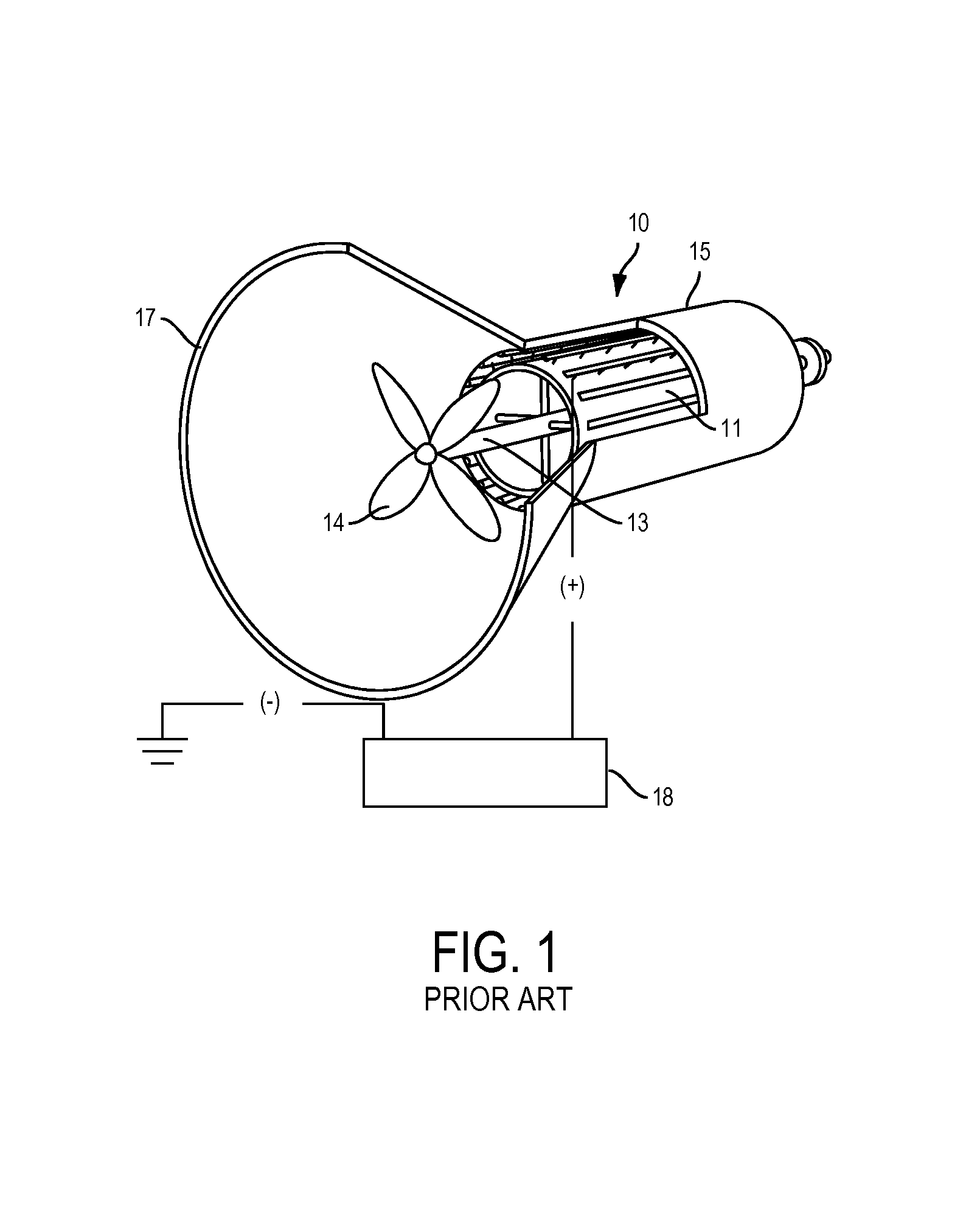
REFERENCES TO RELATED APPLICATION[0001]This application is a Continuation-In Part application of U.S. patent application Ser. No. 14 / 084,234 filed on Nov. 19, 2013.BACKGROUND OF THE INVENTION[0002]1. Field of the Invention[0003]One or more embodiments of the present invention relate to an air power mobile generator including an electric generator and a wind fan rotated by artificial wind produced by moving objects such as automobiles, ships, airplanes, trains, helicopters and the like.[0004]2. Description of the Related Art[0005]Many different kinds of wind mills have been used to generate electricity by capturing natural wind. In order to capture strong wind, there is a need to build a high wind tower with a huge fan at a certain place where strong wind blows. As such, the utility of the wind mills are limited, depend on natural wind, and are costly.[0006]Further, FIG. 1 illustrates a triboelectric power generator 10 disclosed in U.S. patent application Ser. No. 14 / 076,646, which w...

Claims


Application Information

Patent Timeline
Patent Type & Authority Patents(United States)
IPC IPC(8): B61D43/00F02B63/04
CPCB61D43/00Y02T30/36F02B63/04F05B2240/9113F05B2260/4031H02K9/06B60L8/006B60L2200/26Y02T10/7072Y02T30/00
Inventor KIM, KI ILKIM, YOUNGDUNCANSON, SARAH
Owner K TECH INC
Learn More