Pressing member, endoscopic treatment system, and endoscopic suturing device

a technology which is applied in the field of suturing device and endoscopic treatment system, can solve the problems of complicated procedure, difficult to capture the image of the lesion, and difficult to identify the position of the lesion, so as to shorten the procedure time and simplify the procedure

Active Publication Date: 2014-11-04
OLYMPUS CORP
View PDF24 Cites 233 Cited by
  • Summary
  • Abstract
  • Description
  • Claims
  • Application Information

AI Technical Summary

Benefits of technology

[0012]Another object of the present invention is to promote recovery of the lesion after the entire resection.
[0037]Since the suture treatment can be performed in such a manner that the suturing tool is penetrated through the corrugated treatment target portion, it is possible to suture the two biological tissues of the treatment target portion in a state that the two biological tissues are folded in multiple layers. Accordingly, it is possible to suture perforations formed by the resection in a secure manner while maintaining a closed environment until the perforations are coalesced.

Problems solved by technology

However, such an endoscopic treatment system has the following problems.
Accordingly, it has been one of the reasons for the procedure being complicated.
In addition, since the opening is formed on the lateral surface of the overtube, it is difficult to capture the image of the lesion using an image capturing portion provided at the distal end of the endoscope.
Thus, it is difficult to identify the position of the lesion, deteriorating the operability of a treatment tool such as the suturing device.
Although the ligating tool or the suture thread is passed through the alimentary tract so as to substantially overlap with the same, it is difficult to maintain a closed environment until the biological tissue is coalesced.

Method used


Image

  • Pressing member, endoscopic treatment system, and endoscopic suturing device
  • Pressing member, endoscopic treatment system, and endoscopic suturing device
  • Pressing member, endoscopic treatment system, and endoscopic suturing device

Examples


embodiment 1

[0165]Hereinafter, a first embodiment will be described in detail with reference to FIGS. 1 to 28.

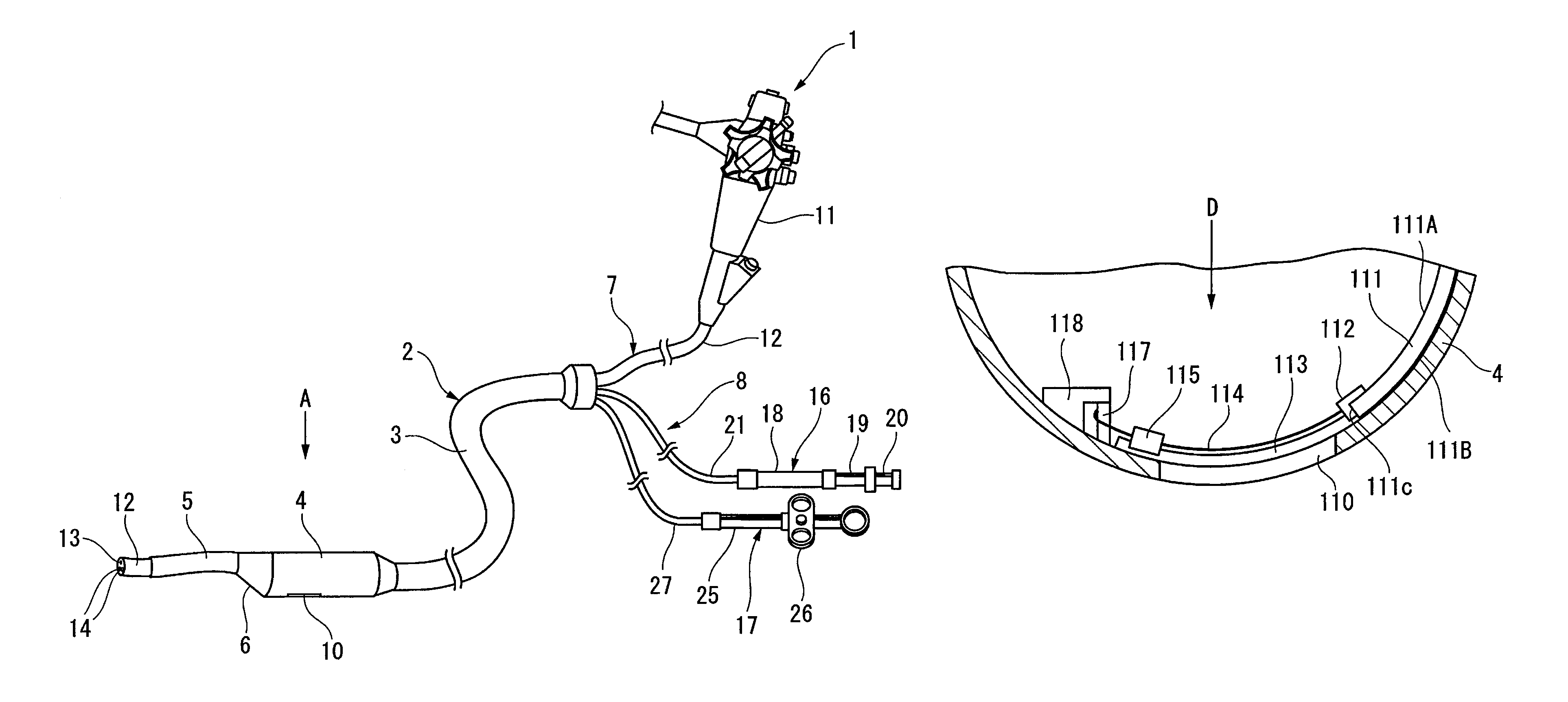
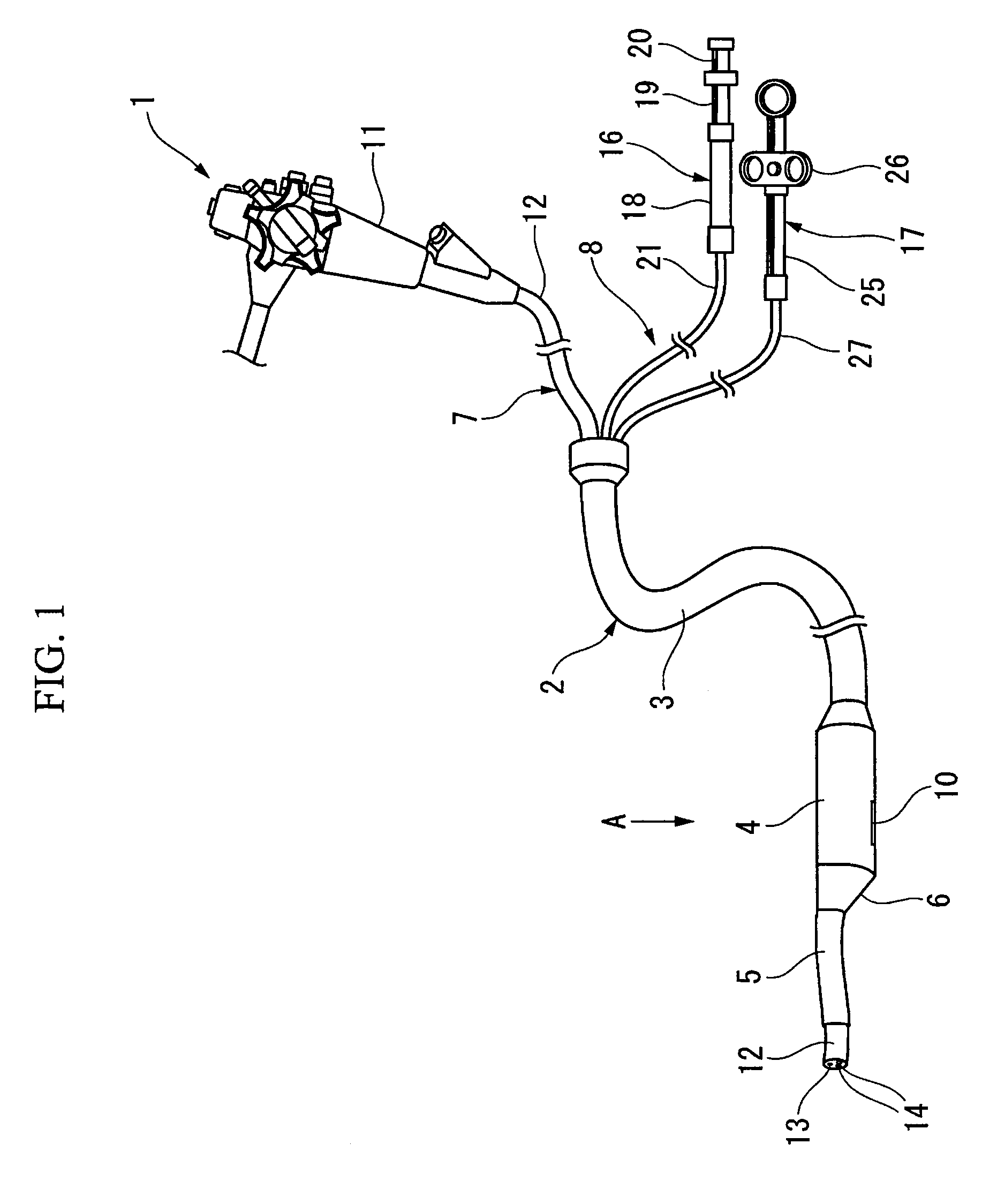
[0166]As shown in FIG. 1, an endoscopic treatment system 1 includes an elongated overtube 2 serving as a pressing member main body that is inserted into the body of a patient. The overtube 2 is provided with a chamber 4 at a distal end of a flexible tube main body 3. The chamber 4 extends in a cylindrical shape while the diameter thereof is enlarged from the distal end portion of the tube main body 3. A flexible insertion guide 5 is provided on the distal end surface of the chamber 4. The insertion guide 5 is a cylindrical member that is located at a position axially offset with respect to the chamber 4. A transitional portion where the distal end portion of the chamber 4 transitions into the insertion guide 5 is formed as a tapered portion 6 that is cut obliquely toward the insertion guide 5.

[0167]On a more proximal side in the longitudinal direction of the chamber 4 than the tapered p...

embodiment 2

[0212]A second embodiment will be described with reference to FIGS. 34 to 39. Components similar or identical to those of the first embodiment will be referenced by the same reference numerals, and overlapping descriptions will be omitted.

[0213]In the present embodiment, the shape of the lateral hole provided on the chamber is different from that of the first embodiment. That is, as shown in FIG. 34, a lateral hole 100 is an entanglement preventing portion that includes an elongated, first opening 101 and a second opening 102 that is provided to be connected to the distal end side of the first opening 101. The first opening 101 has the same length and width as that of the lateral hole 10 according to the first embodiment. The second opening 102 is formed in a substantially circular shape and has a width greater than that of the first opening 101.

[0214]As shown in FIG. 35, during the procedure, the overtube 2 is inserted with the second opening 102 opposed to the lesion W1, the grasp...

embodiment 3

[0219]A third embodiment will be described with reference to FIGS. 40 to 47. Components similar or identical to those of the afore-described embodiments will be referenced by the same reference numerals, and overlapping descriptions will be omitted.

[0220]As shown in the sectional view of FIG. 40, a lateral hole 110 is formed in the chamber 4. The width of the lateral hole 110 in the circumferential direction of the chamber 4 is sufficiently larger than the thickness of the total layers of the lesion W1 to be drawn in. Here, on the inner circumference of the chamber 4, a slider cover 111 serving as the entanglement preventing portion is attached so as to be freely movable in the circumferential direction. The slider cover 111 includes a first surface 111A which is the inner circumferential surface opposed to the endoscope 7, and a second surface 111B which is the outer circumferential surface opposed to the treatment target portion. The slider cover 111 has a size that can cover the ...


PUM


Abstract

An endoscopic treatment system 1 of the present invention includes an overtube 2 that is inserted into the body of a patient. An endoscope 7 and a suturing device 8 are inserted into the overtube 2. The overtube 2 has a long and flexible tube main body 3, and a chamber 4 is provided at the distal end of the tube main body 3. The chamber 4 has a lateral hole 10 formed on the lateral surface thereof. The width of the lateral hole 10 is set such that a lesion can be drawn into the lateral hole 10 while preventing other organs on the periphery of the lesion from being drawn into the lateral hole 10.

Description

CROSS REFERENCE TO RELATED APPLICATION[0001]The present application is a 35 U.S.C. §§371 national phase conversion of PCT / JP2006 / 314527, filed Jul. 21, 2006, which claims priority of Japanese Application No. 2005-213483, filed Jul. 22, 2005, the disclosure of which has been incorporated herein by reference. The PCT International Application was published in the Japanese language.TECHNICAL FIELD[0002]The present invention relates to a pressing member that is inserted into the body and presses a biological tissue when performing an endoscopic treatment and to an endoscopic treatment system having the pressing member. The present invention also relates to an endoscopic suturing device that sutures a biological tissue.[0003]This application is based upon and claims the benefit of priority from the prior Japanese Patent Application No. 2005-213483 filed on Jul. 22, 2005, the entire contents of which are incorporated herein by reference.BACKGROUND ART[0004]When performing a treatment on a...

Claims


Application Information

Patent Timeline
Patent Type & Authority Patents(United States)
IPC IPC(8): A61B17/06A61B17/062A61B17/00A61B17/29A61B1/00A61B1/04A61B18/14A61B17/02A61B17/04A61B17/3205
CPCA61B2018/1407A61B2017/0496A61B17/0487A61B2017/0464A61B17/062A61B2017/00269A61B2017/00296A61B2018/141A61B17/0482A61B2017/00557A61B2017/0409A61B2017/0451A61B2017/2926A61B17/29A61B18/1477A61B18/1492A61B17/0469A61B2017/00292A61B2017/0458A61B17/0401A61B2017/0417A61B2017/06052A61B17/32056A61B2018/1425A61B17/0218
Inventor SAKAMOTO, YUJIOKADA, TSUTOMUMIYAMOTO, SATOSHI
Owner OLYMPUS CORP
Why Eureka
Try Eureka