Switch-driving circuit
a technology of driving circuit and switch, applied in the direction of pulse technique, oscillation generator, power conversion system, etc., can solve the problems of increasing system cost and complexity, increasing optical fiber cost, and longer delay time, and achieve stable and reliable driving signals. fast response
- Summary
- Abstract
- Description
- Claims
- Application Information
AI Technical Summary
Benefits of technology
Problems solved by technology
Method used
Image
Examples
Embodiment Construction
[0030]In the following description, several specific details are presented to provide a thorough understanding of the embodiments of the present invention. One skilled in the relevant art will recognize, however, that the present invention can be practiced without one or more of the specific details, or in combination with other components, etc. In other instances, well-known implementations or operations are not shown or described in detail to avoid obscuring aspects of various embodiments of the present invention.
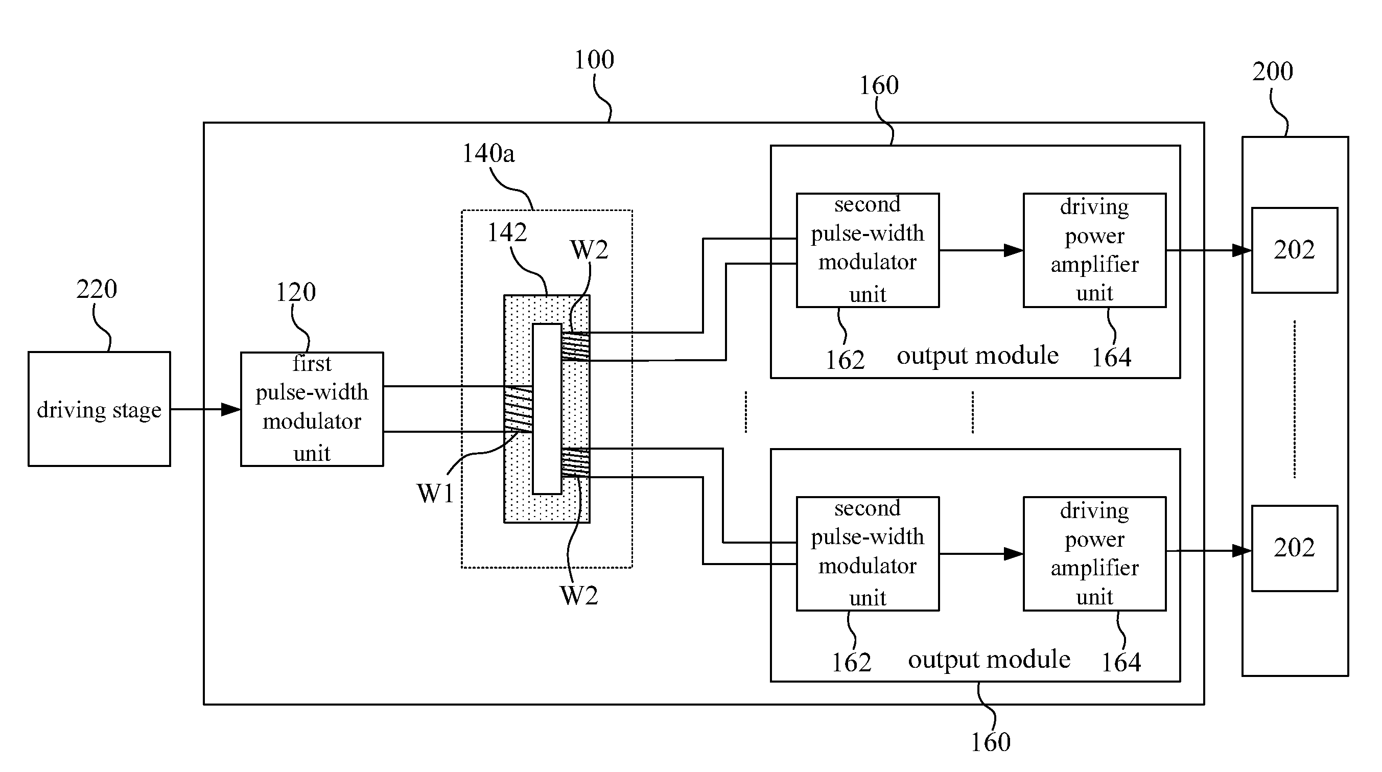
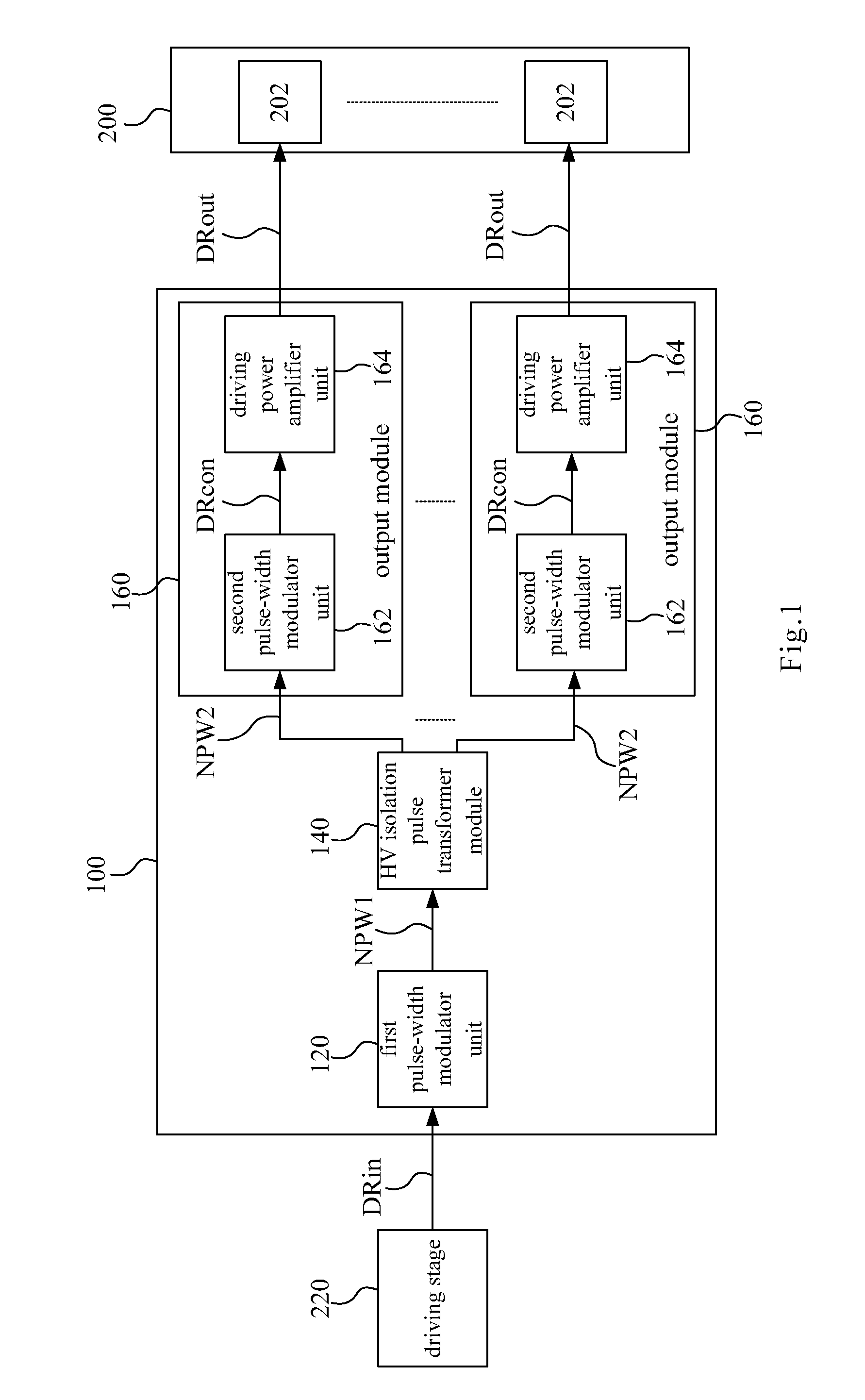
[0031]Reference is made to FIG. 1, which is a function block diagram illustrating a switch-driving circuit 100 according to an embodiment of the disclosure. As shown in FIG. 1, the switch-driving circuit 100 includes a first pulse-width modulator 120, a high-voltage isolation pulse transformer module 140 and a plurality of output modules 160. The switch-driving circuit 100 is coupled between a driving stage 220 and a full-controlled power switch combination 200, and used ...
PUM
 Abstract
Description
Claims
Application Information
 - R&D
- Intellectual Property
- Life Sciences
- Materials
- Tech Scout
- Unparalleled Data Quality
- Higher Quality Content
- 60% Fewer Hallucinations
Browse by: Latest US Patents, China's latest patents, Technical Efficacy Thesaurus, Application Domain, Technology Topic, Popular Technical Reports.
© 2025 PatSnap. All rights reserved.Legal|Privacy policy|Modern Slavery Act Transparency Statement|Sitemap|About US| Contact US: help@patsnap.com


