Section of a separation column, separation column and a method of operation

a separation column and separation column technology, applied in vacuum distillation separation, separation process, carburetor air, etc., can solve the problems of affecting the flow direction, affecting the design of gas/liquid contact devices, and creating extra costs for auxiliary equipment such as pumps, so as to facilitate the distribution of feed

Active Publication Date: 2014-11-18
NESTE OIL OY
View PDF24 Cites 6 Cited by
  • Summary
  • Abstract
  • Description
  • Claims
  • Application Information

AI Technical Summary

Benefits of technology

[0010]An object of the present invention is to facilitate the distribution of feed as it is introduced to a contacting device column.
[0012]More specifically, it is an object to provide a feed distribution device which can be used to distribute the gas or vapor portion of the feed more evenly along the cross-sectional area of a separation section above the feed location compared to the distribution without a feed distribution device. An additional object is to, alone or in conjunction with distributing the feed more evenly, to use the feed distribution device is to reduce the maximum magnitude of local velocity of at least a portion of the feed as it is introduced to the separation section above the feed location.
[0013]A further object of the invention is to provide a solution for distributing the feed without causing a significant pressure drop in the system.
[0014]The above-mentioned objects are achieved by arranging at least one series of plates, with voids between them, known as a feed distribution device substantially in front of one or more feed inlets. The series of plates being arranged in such a position and formation as to sufficiently alter the flow of the inlet feed so that it is more evenly distributed along the cross-sectional area of the separation section above the feed location, and the maximum local velocity of the feed flow entering the separation section is reduced.
[0020]Considerable advantages are achieved by means of the invention. With the addition of one or more feed distribution devices at the point feed is introduced to the system, feed flow properties that are harmful to the interior portion of the system, mainly high velocity, can be mitigated. Additionally, by diverting the direction of the flow so that it is distributed evenly to the cross-sectional area of the separation section above the said feed distribution device increases the efficiency of said separation section and simultaneously allows for minimizing the vertical dimension of column section. By minimizing the vertical dimension of the column section it allows for more cost effective column design and maintenance. Additional advantages to the present invention are that it allows multiple feed inlets to be located closer together, if desired for maintenance and design purposes while maintaining substantially even distribution of the portion of the feed directed to a separation section located above the column section in question as well as minimizing pressure loss in said section the column.
[0027]According to a preferred embodiment, the feed inlet is connected to an output of a device, such as a reboiler, which produces a flashing feed to the column. The plates of the at least one feed distribution device are arranged to deflect and reduce the magnitude of the velocity of at least a portion of the flash feed. The invention has particular benefits in the case of flashing feeds which as such would produce an uneven flow distribution into the separation section above the feed inlet, thus reducing separation efficiency.

Problems solved by technology

This high velocity makes any abrupt changes in the direction of flow difficult.
The high velocity of these streams creates challenges to the design of gas / liquid contacting devices.
Additionally, increased contacting device height at this point / part also creates extra cost for auxiliary equipment such as pumps, as they have to be designed for increased capacity parameters (such as pump head).
Further cost items impacted by increased contacting device height include structural steel, cabling, foundations etc.

Method used


Image

  • Section of a separation column, separation column and a method of operation
  • Section of a separation column, separation column and a method of operation
  • Section of a separation column, separation column and a method of operation

Examples


Embodiment Construction

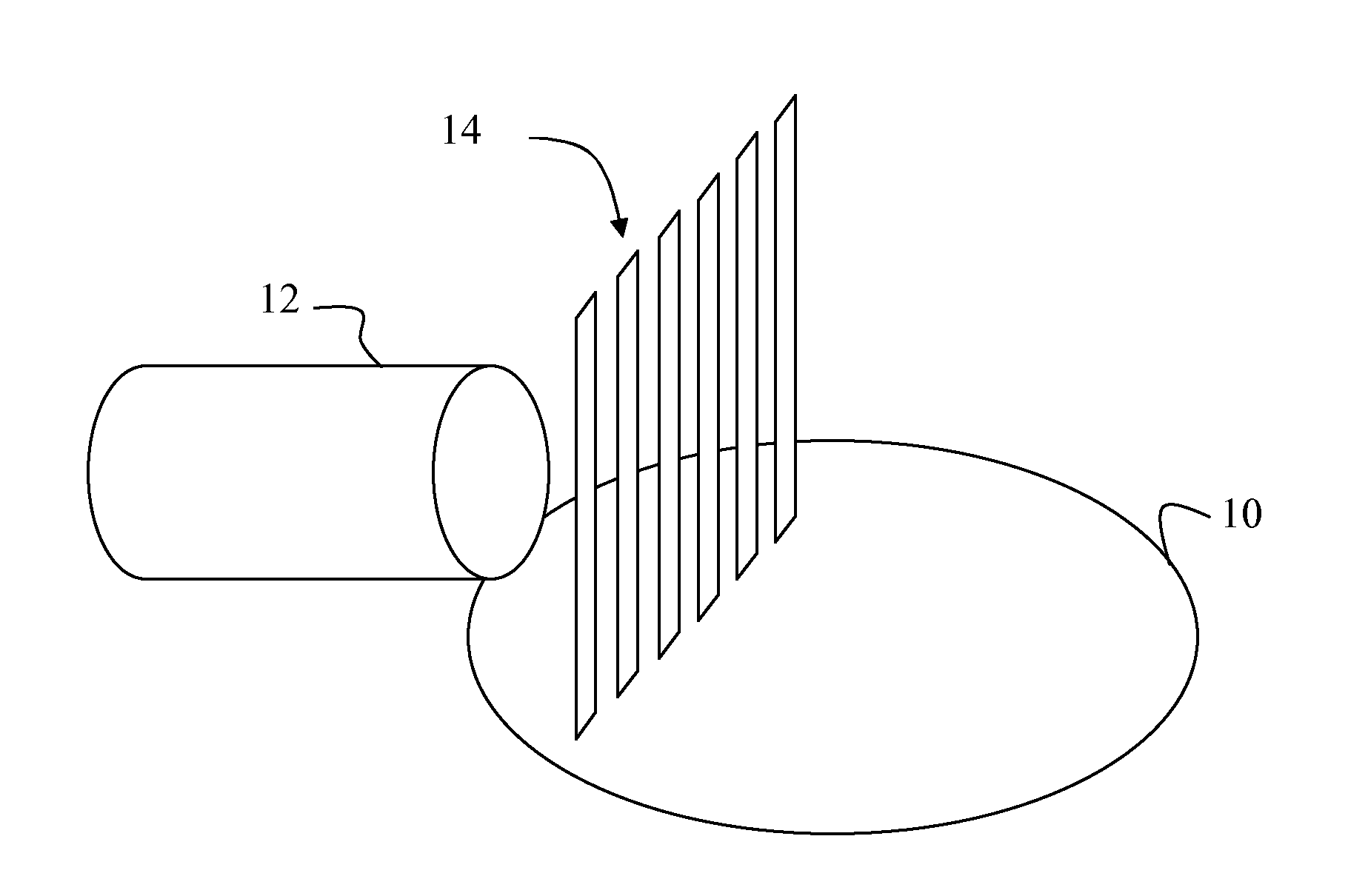
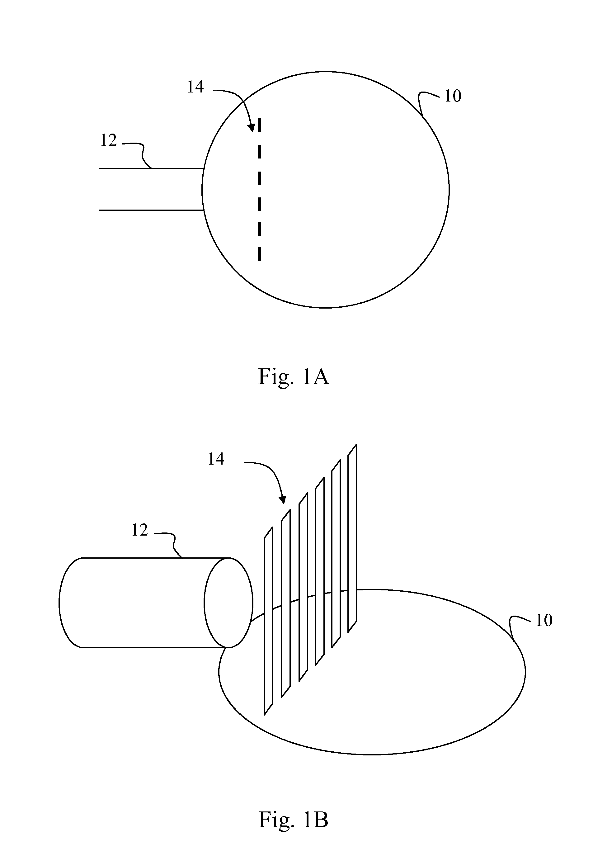
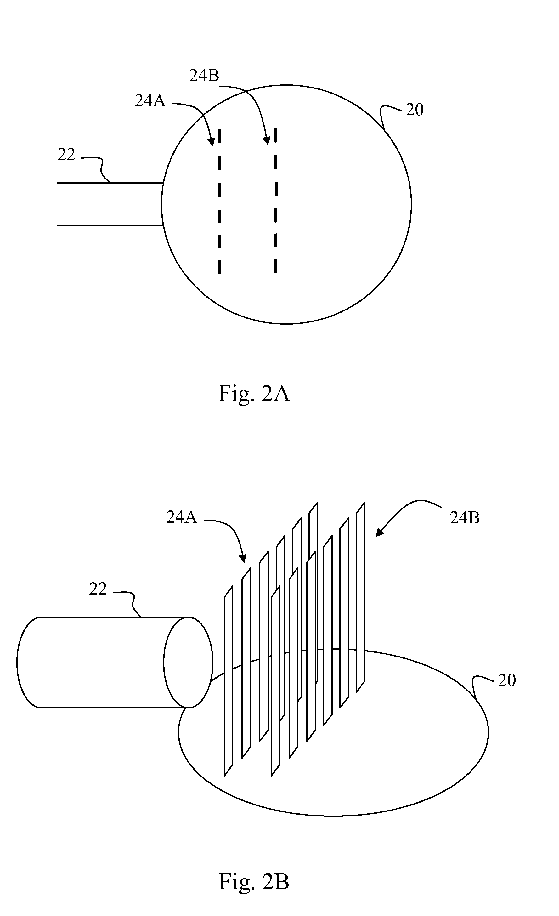
[0042]There are numerous types and variations of contacting device columns. Some of the standard contacting device columns are distillation columns, stripping columns, absorption columns, extraction columns and washing columns. In addition to columns with a single purpose, many contacting columns are combinations of two or more standard processes (i.e. distillation and absorption). Further, there are categories such as packed columns and vacuum columns. One of ordinary skill in the art will recognize the applicability for the present invention in all of the types and variations of contacting devices enumerated above in addition to those not specifically enumerated but art recognized.

[0043]According to one embodiment, the contacting device column has at least one feed inlet and at least two outlets, one outlet for each portion of the feed to be separated in the column. In many cases there is a flow loop in which a stream is taken from the column, the stream is heated and the stream i...


PUM

PropertyMeasurementUnit
angleaaaaaaaaaa
anglesaaaaaaaaaa
diameteraaaaaaaaaa

Abstract

A separation column containing a feed distribution device and a feed distribution device for a separation column, such as a vacuum distillation column. The feed distribution device being capable of diffusing and directing a feed flow from a feed inlet so as to distribute the feed substantially evenly over the surface area of a separation plate in the column thereby increasing the columns efficiency. The separation column containing the feed distribution device being capable of shorter height, less costly design and lower operating cost than a separation column without the feed distribution device.

Description

CROSS-REFERENCE TO RELATED DOCUMENTS[0001]The present patent application claims priority to Provisional Patent Application Ser. No. 61 / 327,112 filed Apr. 23, 2010, the complete disclosure of which is incorporated herein by reference.FIELD OF THE INVENTION[0002]The present invention relates to separation columns, in particular to distillation columns in which the feed is a gas, liquid or gas / liquid mixture. Such columns contain a section of column into which a feed flow is directed from one or more inlets. More particularly, the invention concerns improving the distribution of feed flow in such sections.BACKGROUND OF THE INVENTION[0003]In a distillation column where at least one of the feed streams contains a gas / liquid mixture, with a large fraction of the gas produced by a vaporization means upstream of the distillation column, it is necessary that the gas be directed to a separation section above the feed stream location. Usually it is desirable to separate the liquid from the gas...

Claims


Application Information

Patent Timeline
Patent Type & Authority Patents(United States)
IPC IPC(8): B01D45/08B01D53/18B01F3/04B01D3/00
CPCB01D53/185B01D3/008B01D45/08B01D3/10B01D3/32
Inventor TAMMINEN, ESASUTINEN, JARI
Owner NESTE OIL OY
Why Eureka
Try Eureka