Extended low contrast detectability for radiographic imaging systems

a radiographic imaging and low contrast technology, applied in the field of radiographic imaging, can solve the problems of increased radiation dosage, increased image noise, and insufficient current lcd specification, and achieve the effect of low dose scans and good image quality

Active Publication Date: 2014-11-18
TIP IMAGING LLC DBA PLEXAR IMAGING
View PDF5 Cites 23 Cited by
  • Summary
  • Abstract
  • Description
  • Claims
  • Application Information

AI Technical Summary

Benefits of technology

[0049]The present disclosure and related inventions are of an Extended Low Contrast Detectability (also referred to herein as “ExLCD” or “Extended LCD”) contrast measurement system and method that provides a robust capability to connect x-ray dose with a universal image quality metric. The disclosure and related inventions provide the capability to:
[0053]4. optimize the scanning protocol on a specific radiographic imaging system for a specific patient in a clinical scenario for a desired contrast index level, thereby enabling a radiographic imaging system's ability to perform lower dose scans with good image quality.

Problems solved by technology

An important issue in radiology today is how to reduce the radiation dose during CT examinations without compromising the image quality.
Generally, higher radiation doses result in the ability to detect lower contrast smaller objects, while lower doses lead to increased image noise.
Increased radiation dosage increases the risk of radiation induced cancer.
In this description, it will be shown that the current LCD specification is inadequate in that it characterizes the performance of the CT scanner at only one protocol and that it is necessary to characterize the performance over an extended range including, for example, the full operating range of the scanner.
Also, contrast is significantly impacted by non-linear reconstruction methods as well as the reconstruction pixel size and reconstruction filter.
Smaller values of Contrast Index indicate poorer image quality or the ability to detect only larger, higher contrast objects.
However the statistical method cannot differentiate contrast performance resulting from non-linear reconstruction methods since only a noise image is evaluated.
In fact, it significantly misconstrues the true contrast performance of the scanner.
Additionally, the current LCD methods do not adequately handle smaller pins, those that are impacted by system blurring, i.e. the Modulation Transfer Function (MTF).
Given reconstruction processes that limit spatial bandwidth of both noise and object, conventional detectability methods will not account for changes in the assumed object.
In the lower plot, the representative CT scanner performance curves are overlaid on the error region of the single protocol contrast method, illustrating that the inaccuracies of the current LCD method may effectively prohibit true differentiation of the contrast performance between CT scanners.

Method used


Image

  • Extended low contrast detectability for radiographic imaging systems
  • Extended low contrast detectability for radiographic imaging systems
  • Extended low contrast detectability for radiographic imaging systems

Examples


Embodiment Construction

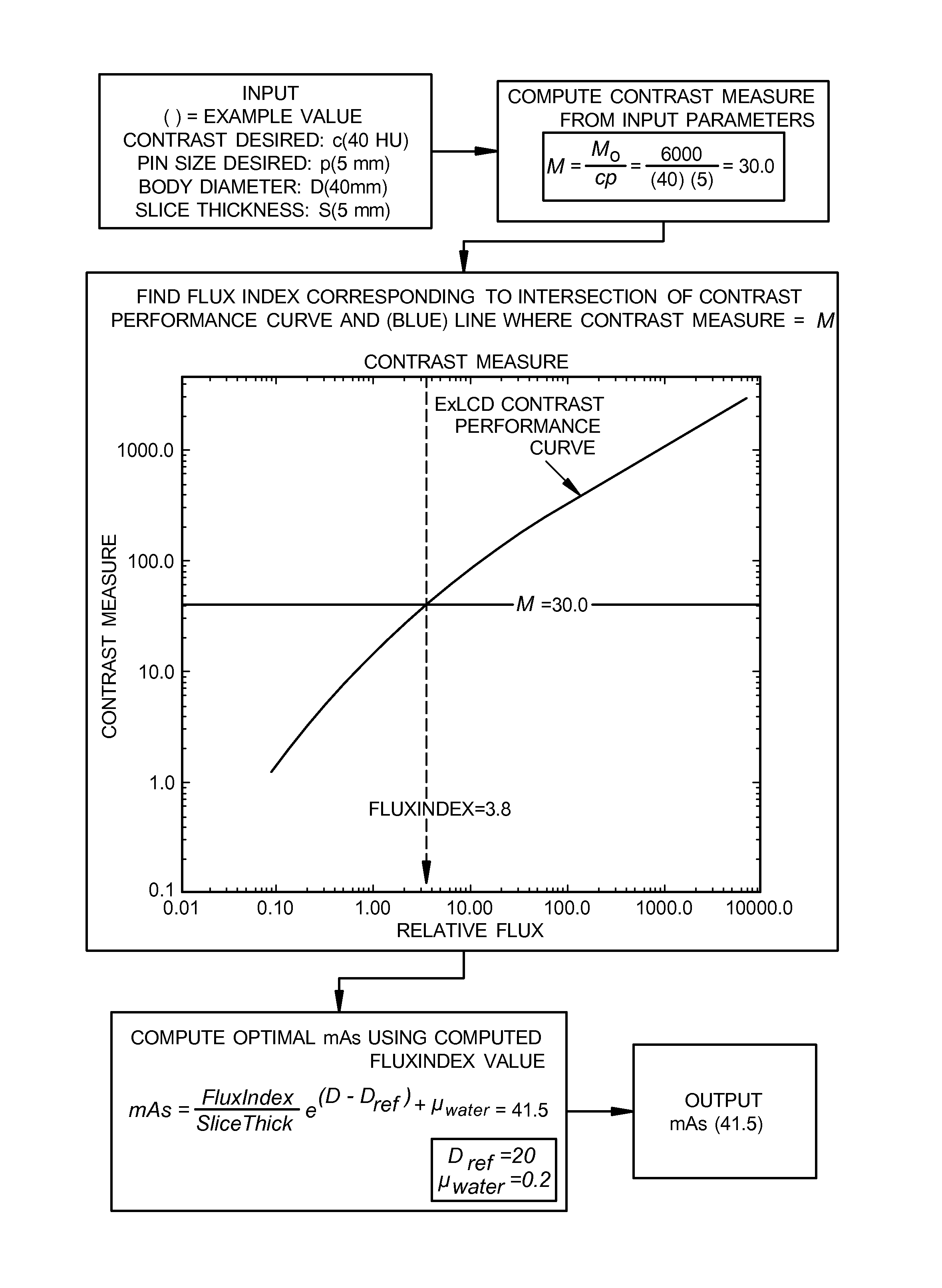
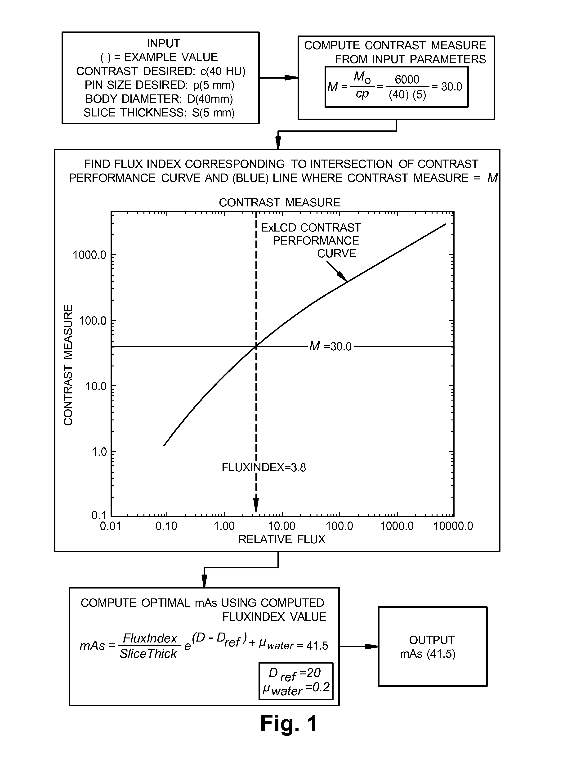
[0101]FIG. 1 shows a representative data flow example for an optimal protocol selection process in accordance with the disclosure and related inventions. Assume that an ExLCD Performance Function is available for a scanner or particular radiographic imaging system. A desired contrast level is selected based on the clinical image quality requirements. In this example, the desired Contrast Index is 30.0 corresponding to a 5 mm pin at a contrast level of 40 Hounsfeld Units (HU). The Optimal Protocol Selection then determines the location on the Contrast Performance Curve corresponding to the desired Contrast Index. Since the ExLCD Performance Function is always monotonic, there will be a unique Flux Index value corresponding to the intersection of the Contrast Index value and the ExLCD Performance Function as illustrated in the graph on FIG. 1. For this example, the Flux Index value determined is 3.8. This unique Flux Index value can then be used to determine the optimal protocol.

[0102...


PUM


Abstract

Systems and methods for determining an extended low contrast detectability performance function for an operating range for a core operating mode of a radiographic imaging system using actual reconstructed images characterize the contrast performance of a radiographic imaging system over its operating range and for any patient size based on the off-line calibration, uses ordered pairs of flux index and contrast index for each scanned object to provide a contrast index for each protocol for each contrast set, and uses the ordered pairs of flux index and contrast index to determine an extended low contrast detectability performance function for the operating range of a radiographic imaging system. Extended low contrast detectability performance data compilation and methods of clinical use, and low contrast phantom configurations and methods of calibration are also disclosed.

Description

RELATED APPLICATIONS[0001]This application claims priority to U.S. Provisional Patent Application No. 61 / 271,150 filed Jul. 17, 2009 and U.S. Provisional Patent Application No. 61 / 278,954, filed Oct. 14, 2009, both of which are incorporated herein by reference.FIELD OF THE INVENTION[0002]The present invention is in the general field of radiology and imaging, and more particularly in the field of radiographic imaging.BACKGROUND OF THE INVENTION[0003]Because radiographic imaging, including computed tomography (CT) has the capability of detecting small low contrast features, it has become an integral part of radiology medical practice, allowing medical practitioners to detect low contrast tumors and lesions in soft tissue anatomical regions including the brain and the liver. Low contrast detection is an important characteristic of diagnostic x-ray imaging methods. An important issue in radiology today is how to reduce the radiation dose during CT examinations without compromising the i...

Claims


Application Information

Patent Timeline
Patent Type & Authority Patents(United States)
IPC IPC(8): G06K9/00A61B6/00A61B6/03
CPCA61B6/032A61B6/545A61B6/583A61B6/482A61B6/405A61B6/5252A61B6/542A61B6/587
Inventor ROHLER, DAVID P.MANIYEDATH, ARJUN K.TOTH, THOMAS L.DECHANT, THOMAS E.IZEN, STEVEN H.
Owner TIP IMAGING LLC DBA PLEXAR IMAGING
Why Eureka
Try Eureka