Vehicle-body front structure

a front structure and vehicle technology, applied in the direction of roofs, transportation and packaging, vehicle arrangements, etc., can solve the problems of improper deformation of the apron frame outwardly in the vehicle width direction, the disconnection of the hinge pillar and the dash panel, and the difficulty of ensuring an appropriate vehicle function

Inactive Publication Date: 2014-12-02
MAZDA MOTOR CORP
View PDF15 Cites 8 Cited by
  • Summary
  • Abstract
  • Description
  • Claims
  • Application Information

AI Technical Summary

Benefits of technology

[0010]An object of the present invention is to provide a vehicle-body front structure which can restrain the apron frame from deforming outwardly in the vehicle width direction in the vehicle frontal collision so as to prevent the dash panel from moving back into the vehicle compartment too much.
[0012]According to the present invention, since the apron frame provided on the outside of the front side frame in the vehicle width direction is connected to the vertical branch brace via the deformation restraint member, even when the collision load is inputted to the apron frame from the vehicle front in the vehicle frontal collision, the apron frame can be restrained from deforming outwardly in the vehicle width direction. That is, the rigidity around a connection portion of the hinge pillar to the side end portion of the dash panel can be improved, so that it can be properly prevented that the connection portion of the hinge pillar to the dash panel is broken, thereby the hinge pillar and the dash panel are disconnected. Thus, the dash panel can be restrained from moving back into the vehicle compartment too much even in the case of the load being inputted to the dash panel from the vehicle front in the vehicle frontal collision. Further, since the closed cross section is formed by the inner face of the suspension tower and the vertical branch brace, the vertical branch brace can reinforce the suspension tower properly, thereby restraining deformation of the suspension tower.
[0014]According to an embodiment of the present invention, the deformation restraint member is connected to a rear end portion of the suspension tower. Thereby, even when it is inputted to the suspension tower from the vehicle front in the vehicle frontal collision, the collision load can be transmitted and dispersed to the vertical branch brace and the apron frame through the deformation restraint member. Thus, an efficient disperse of the collision load to the vehicle rear can be achieved, so that an impact applied to the suspension tower can be decreased, and retreat and deformation of the suspension tower can be restrained. Accordingly, the transmission and disperse of the collision load via the vertical branch brace can be achieved efficiently. Further, while it is considered that a large load may be inputted to the suspension tower from a front wheel via a front suspension in the vehicle frontal collision, since the large load inputted to the suspension tower can be transmitted and dispersed to the vertical branch brace and the apron frame through the deformation restraint member, the retreat and deformation of the suspension tower can be restrained as well.
[0015]According to another embodiment of the present invention, the deformation restraint member, the vertical branch brace, the dash panel, and the apron frame form a closed space. Thereby, the rigidity of the vehicle rear body in back of the suspension tower can be improved. Accordingly, the collision load from the vehicle front can be efficiently transmitted and dispersed to the vehicle rear.
[0016]According to another embodiment of the present invention, the deformation restraint member is comprised of a plate member which extends vertically. Thereby, the lightweight vehicle structure can be provided, ensuring the appropriate vehicle function against collisions.

Problems solved by technology

In this case, however, there is a problem in that excessive thinness or decrease in number may cause difficulties in ensuring an appropriate vehicle function against collisions.
For example, in a case in which the above-described lightweight structure is applied to a front portion of the vehicle body which comprises a pair of hinge pillars extending vertically from both side end portions of a dash panel and a pair of apron frames extending forwardly from the hinge pillars, there is a problem in that the apron frames may improperly deform outwardly in a vehicle width direction in a vehicle frontal collision.
This outward deformation of the apron frames may cause a large load outwardly acting on the hinge pillars connected to rear portions of the apron frames, so that there is a concern that a connection portion of the hinge pillar to the side end portion of the dash panel may be broken, thereby the hinge pillar and the dash panel may be disconnected and the load inputting to the dash panel may not be transmitted to the hinge pillar.
Accordingly, when a power train, such as an engine or motor, retreats in the vehicle frontal collision, this retreat of the power train may cause the dash panel to move back into a vehicle compartment too much, thereby deteriorating the appropriate vehicle function against collisions.
This structure, however, merely aims at the efficient transmission and dispersion of the collision load inputted to the front side frame toward the vehicle rear, and it does not restrain the apron frame from deforming outwardly in the vehicle width direction.

Method used


Image

  • Vehicle-body front structure
  • Vehicle-body front structure
  • Vehicle-body front structure

Examples


Embodiment Construction

[0024]Hereafter, a preferred embodiment of the present invention will be descried referring to the accompanying drawings.

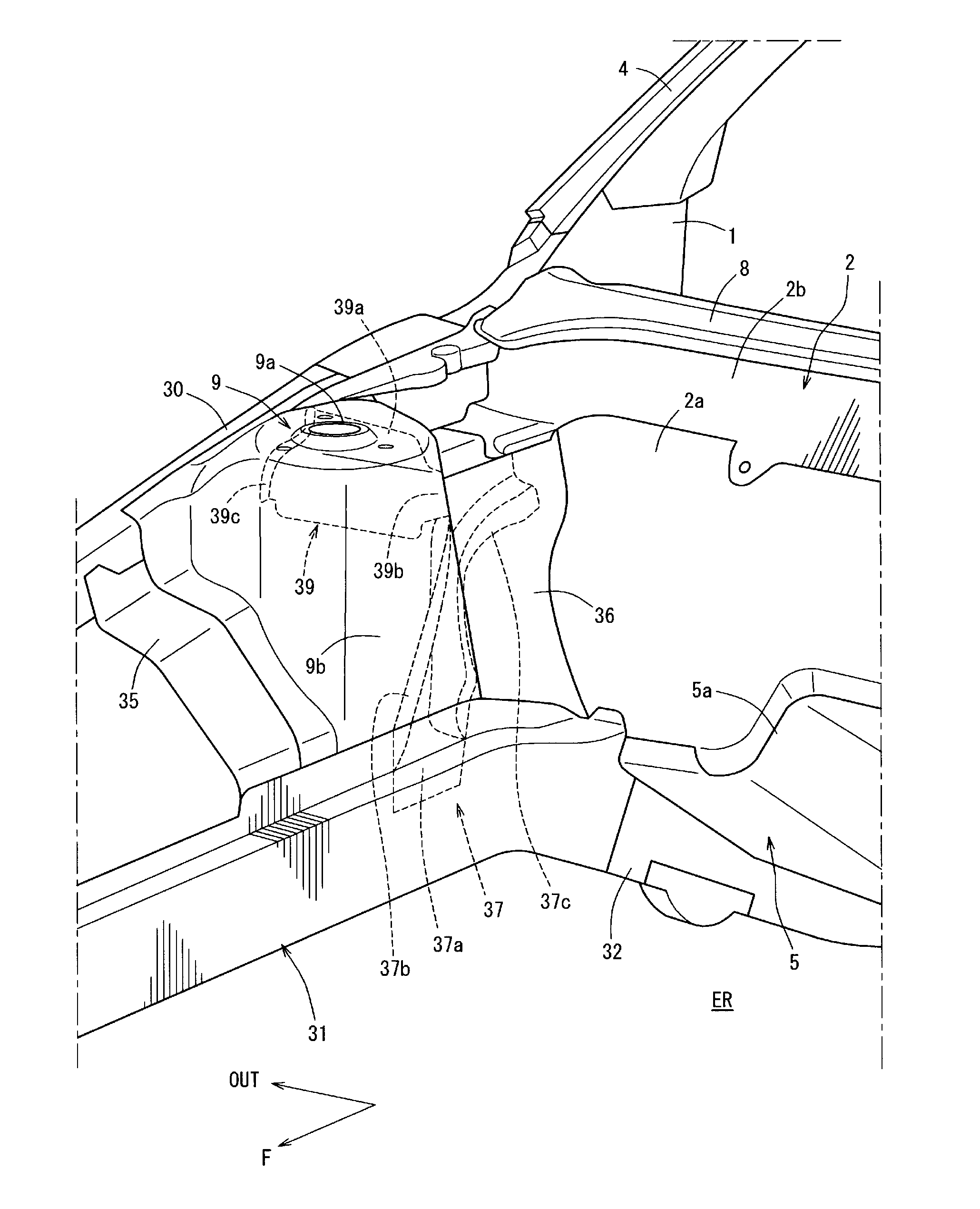
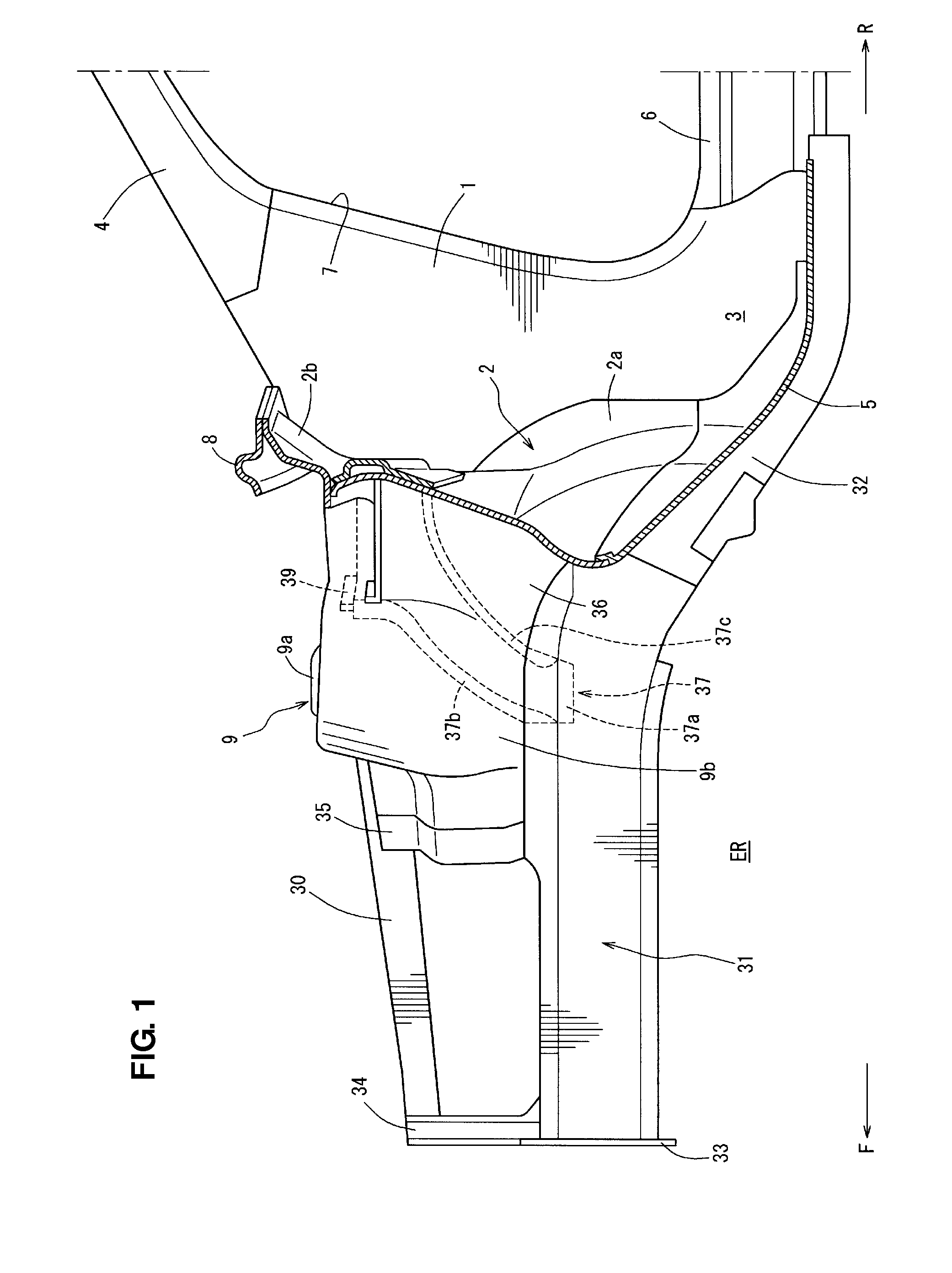
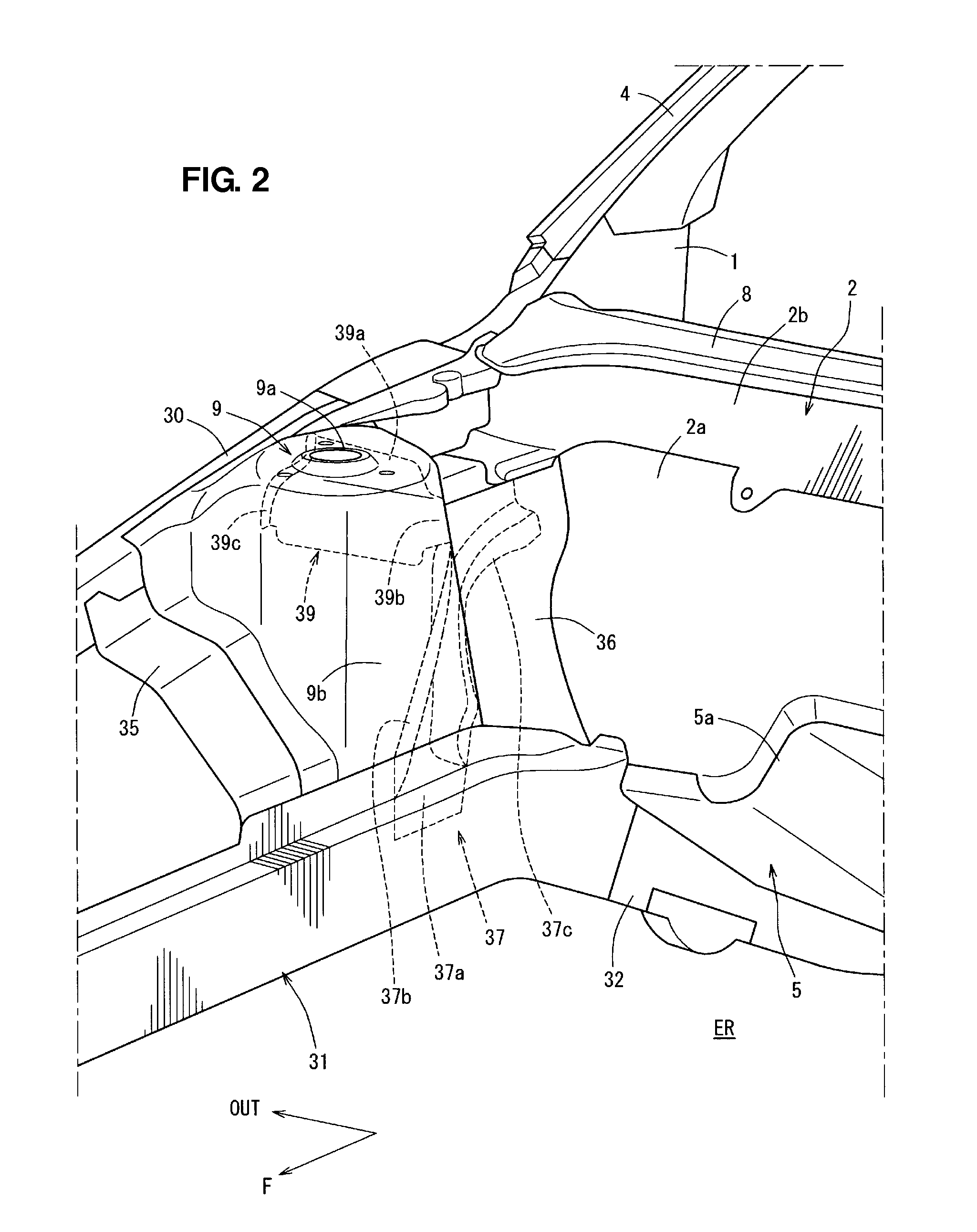
[0025]FIG. 1 is a side view of a vehicle-body front portion, when viewed from a vehicle center in a vehicle width direction, and FIGS. 2 and 3 are a perspective view and a plan view of FIG. 1, respectively. FIG. 4 is a sectional view taken along line A-A of FIG. 3, FIG. 5 is a sectional view taken along line B-B of FIG. 4, and FIG. 6 is a perspective view of a major part of the vehicle-body front portion, when viewed from below. In these figures, an arrow F shows a vehicle front side, an arrow R shows a vehicle rear side, an arrow IN shows a vehicle inside, and an arrow OUT shows a vehicle outside.

[0026]As shown in FIGS. 1 and 2, a pair of hinge pillars 1, 1 (only a right-side hinge pillar is shown in the drawings) is provided at both sides of the vehicle. The hinge pillar 1 is a vehicle-body rigidity member which comprises a hinge pillar outer 1a (see FIG. 5) and...


PUM


Abstract

A rear apron panel is provided between a suspension tower and a dash panel. A vertical branch brace is provided to extend upwardly from a front side frame along an inner face of a suspension tower to form a closed cross section with a rear portion of the suspension tower. A deformation restraint member interconnects the apron frame and the vertical branch brace. Accordingly, there is provided a vehicle-body front structure which can restrain the apron frame from deforming outwardly in the vehicle width direction in the vehicle frontal collision to prevent the dash panel from moving back into the vehicle compartment too much.

Description

BACKGROUND OF THE INVENTION[0001]The present invention relates to a vehicle-body front structure which comprises a front side frame extending forwardly from a side portion of a dash panel of a vehicle, a hinge pillar extending vertically from a side end portion of the dash panel, and an apron frame provided on an outside of the front side frame in a vehicle width direction and extending forwardly from the hinge pillar.[0002]It has been one of main subjects to make lightweight vehicles in order to improve the fuel economy (gas millage) and the like, and various researches and developments for these have been conducted up to date.[0003]Making the thickness of frames and other members constituting a vehicle body thinner or decreasing the number of frames and the like are one of measures for making lightweight vehicles. In this case, however, there is a problem in that excessive thinness or decrease in number may cause difficulties in ensuring an appropriate vehicle function against col...

Claims


Application Information

Patent Timeline
Patent Type & Authority Patents(United States)
IPC IPC(8): B62D21/15B62D25/08
CPCB62D25/088
Inventor KIDO, HIROTOFUKUSHIMA, MASANOBUKIZAKI, ISAMUNAKAMURA, SATOSHIKAWASAKI, KEIZOHASHIMOTO, MANABU
Owner MAZDA MOTOR CORP
Why Eureka
Try Eureka