Methods and devices that employ thermal control of current to electrical components

a technology of electrical components and thermal control, applied in the field of electric powered devices, can solve the problems of radically affecting the incandescent bulb, the service life of the flashlight's light source, and the battery life of the led-based flashlight, so as to achieve efficient use of power supplies and greater service life

Inactive Publication Date: 2014-12-02
UNDERWATER KINETICS
View PDF20 Cites 0 Cited by
  • Summary
  • Abstract
  • Description
  • Claims
  • Application Information

AI Technical Summary

Benefits of technology

[0010]The objects of this invention include the provision of patentable, electrically powered devices that use one or more thermally responsive current-controlling elements to regulate the flow of electricity from the device's power supply to an electrical component such as a light source. Such devices more efficiently utilize power supplies and also provide for greater service lives of the electrical components to which the supply of electric power is regulated.
[0015]Another aspect relates to methods of illuminating articles or spaces using a flashlight according to the invention. Still another aspects of the invention relate to methods of controlling current use, battery life, levels of light output, extending light source life, etc. through the use of a device, particularly a flashlight, that includes a light assembly according to the invention.

Problems solved by technology

As with traditional flashlights, however, the use of LED-based flashlights is also typically constrained by battery life.
Also, the service life of a flashlight's light source, be it an incandescent bulb, LED, or other light source, can be radically affected by operating temperature.

Method used


Image

  • Methods and devices that employ thermal control of current to electrical components
  • Methods and devices that employ thermal control of current to electrical components
  • Methods and devices that employ thermal control of current to electrical components

Examples


Embodiment Construction

[0022]The invention will be further described by reference to the drawings, which are described in detail below. This description shall in no way to be considered to limit the scope of the invention in any manner.

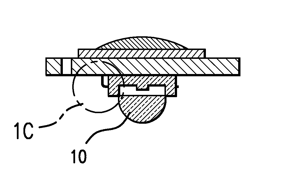
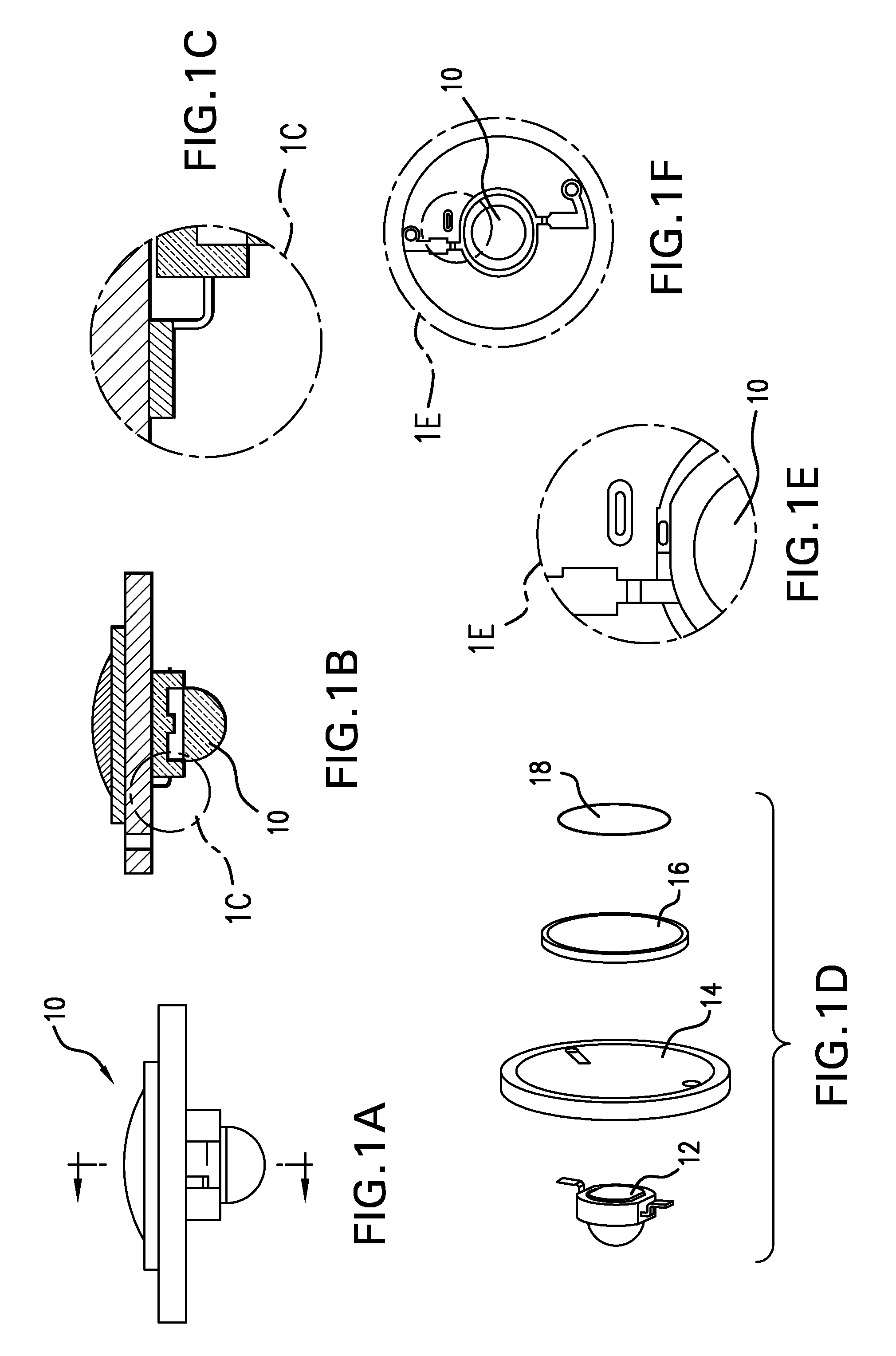
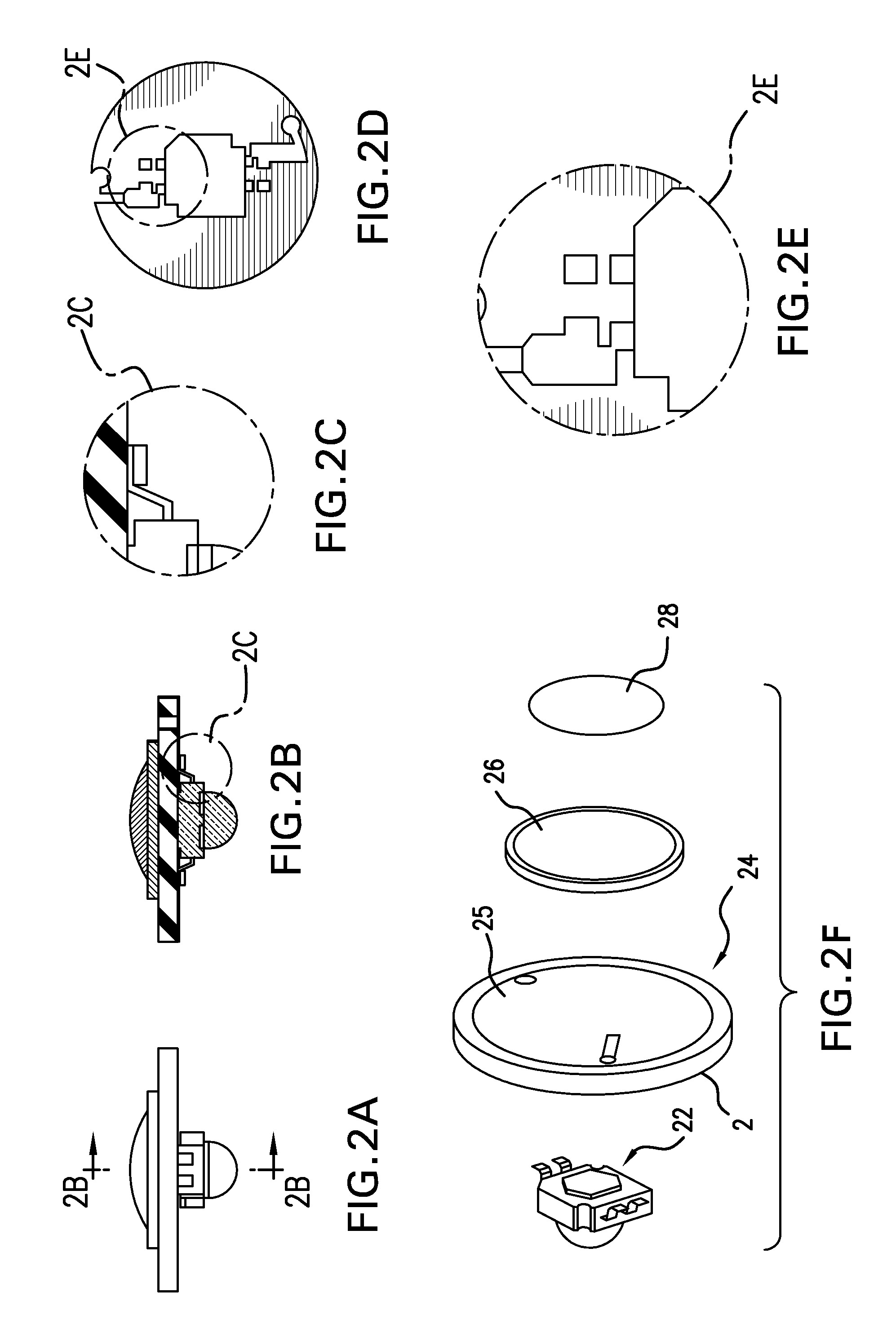
[0023]FIG. 1 shows a representative light assembly (10) according to the invention. This assembly (10) includes an LED (12; 3 watt; Luxeon) attached (in this embodiment, via a suitable epoxy) to a printed circuit board (PCB; 14; for a 3 watt LED). The leads of the LED are aligned with conductors that traverse the PCB in order to provide electrical communication between electrical components positioned on or adjacent to the opposite faces of the PCB. A thermistor (16) is attached (in this embodiment, via a suitable electrically conductive solder) via one surface to the PCB surface opposite the PCB surface to which the LED (12) is attached. A suitable electrically conductive solder (18) is also applied, as required, to a portion of the face of the thermistor (16) opposite tha...


PUM


Abstract

Methods and devices are described that use one or more thermally responsive current-controlling elements to regulate current flow to an electrical component, particularly a light source such as an LED. Examples of such thermally responsive current-controlling elements include thermistors, inductors, and capacitors. for treating conditions or disorders which can be alleviated by reducing food intake are disclosed which comprise administration of an effective amount of a purine analog, alone or in conjunction with other compounds or compositions that affect satiety. The methods are useful for treating conditions or disorders wherein appetite reduction would be beneficial, including obesity and binge-eating disorder. Pharmaceutical compositions for use in the methods of the invention are also disclosed.

Description

TECHNICAL FIELD OF THE INVENTION[0001]The present invention relates to electrically powered devices and methods that employ one or more thermally responsive current-controlling elements to regulate current flow to an electrical component, particularly a light source.BACKGROUND OF THE INVENTION[0002]1. Introduction[0003]The following description includes information that may be useful in understanding the present invention. It is not an admission that any such information is prior art, or relevant, to the presently claimed inventions, or that any publication specifically or implicitly referenced is prior art.[0004]2. Background[0005]Flashlights are popular devices, and have many applications. Traditionally, flashlights have employed an incandescent light bulb as the light source. Recently, flashlights have been introduced that use light emitting diodes (LEDs) as the light source. LEDs offer many advantages over traditional incandescent bulbs, including greater efficiency and durabili...

Claims


Application Information

Patent Timeline
Patent Type & Authority Patents(United States)
IPC IPC(8): F21Y101/02F21L4/00F21V23/04F21V29/00F21L4/04F21L4/02
CPCF21V23/0414F21Y2101/02F21L4/027F21V29/20F21V29/004F21V29/508F21Y2115/10F21V29/70
Inventor UKE, ALAN K.FISCHER, ELMER FREDERICKGIUNTOLI, DAVID M.GUNDERSON, RICHARD H.
Owner UNDERWATER KINETICS
Why Eureka
Try Eureka