Method for making carbon nanotube field emitter

a carbon nanotube and emitter technology, applied in the manufacture of electric discharge tubes/lamps, discharge tube main electrodes, and electronic systems, etc., can solve the problems of increasing the emission voltage, damage to the emission tip of the field emitter, and further damage to the entire field emitter

Active Publication Date: 2014-12-02
TSINGHUA UNIV +1
View PDF4 Cites 6 Cited by
  • Summary
  • Abstract
  • Description
  • Claims
  • Application Information

AI Technical Summary

Benefits of technology

[0060]Referring to FIG. 6, an embodiment of the method for making the carbon nanotube field emitter 30 is shown where before cutting off the triangle region 14 from the carbon nanotube film, the triangle region 14 is treated to a plurality of carbon nanotube strings 34 with the organic solvent 24. In this embodiment, the carbon nanotube wire 16 is formed by shrinking the portion of the carbon nanotube film with the organic solvent 24. In detail, the triangle region 14 is soaked by sprinkling the organic solvent 24, and some adjacent carbon nanotubes in the triangle region 14 would be bundled together to form a carbon nanotube string 34, due to the action of the surface tension of the organic solvent 24. FIG. 7 shows a scanning electron microscope image of a carbon nanotube film including some carbon nanotube strings. This is the result of carbon nanotube film that has been treated with the organic solvent 24 to form some carbon nanotube strings. In one aspect, due to the decrease of the specific surface area via bundling, the mechanical strength and toughness of the triangle region 14 treated with the organic solvent 24 are increased, the coefficient of friction of the triangle region 14 treated with the organic solvent 24 is reduced. In the other aspect, the sticky property of the triangle region 14 treated with the organic solvent 24 is reduced. Therefore, the triangle region 14 is treated into a plurality of carbon nanotube strings 34. One end of the plurality of carbon nanotube strings 34 is aggregated together and joined with the carbon nanotube wire 16. The other end of the plurality of carbon nanotube strings 34 has a fan-shaped divergence. The carbon nanotube strings 34 are wire-like structures within the film. Each of the plurality of carbon nanotube strings 34 includes a plurality of carbon nanotubes joined end-to-end by van der Waals attractive force. The plurality of carbon nanotubes in each of the carbon nanotube strings 34 is parallel to an axis of each of the carbon nanotube strings 34. There is a larger distance between two adjacent carbon nanotube strings 34, further reducing the shielding effect between two adjacent carbon nanotube strings 34.

Problems solved by technology

But improving the emission voltage will damage an emission tip of the field emitter.
The damage to emission tips further damages the entire field emitter.
Therefore, how to solve the shielding effect between two adjacent carbon nanotubes is a problem in application of a carbon nanotube field emitter.
But the strength of the end of the carbon nanotube field emitter is not very high, affecting stability of emitting electrons, and limiting the widespread use of the carbon nanotube field emitter.

Method used


Image

  • Method for making carbon nanotube field emitter
  • Method for making carbon nanotube field emitter
  • Method for making carbon nanotube field emitter

Examples


first embodiment

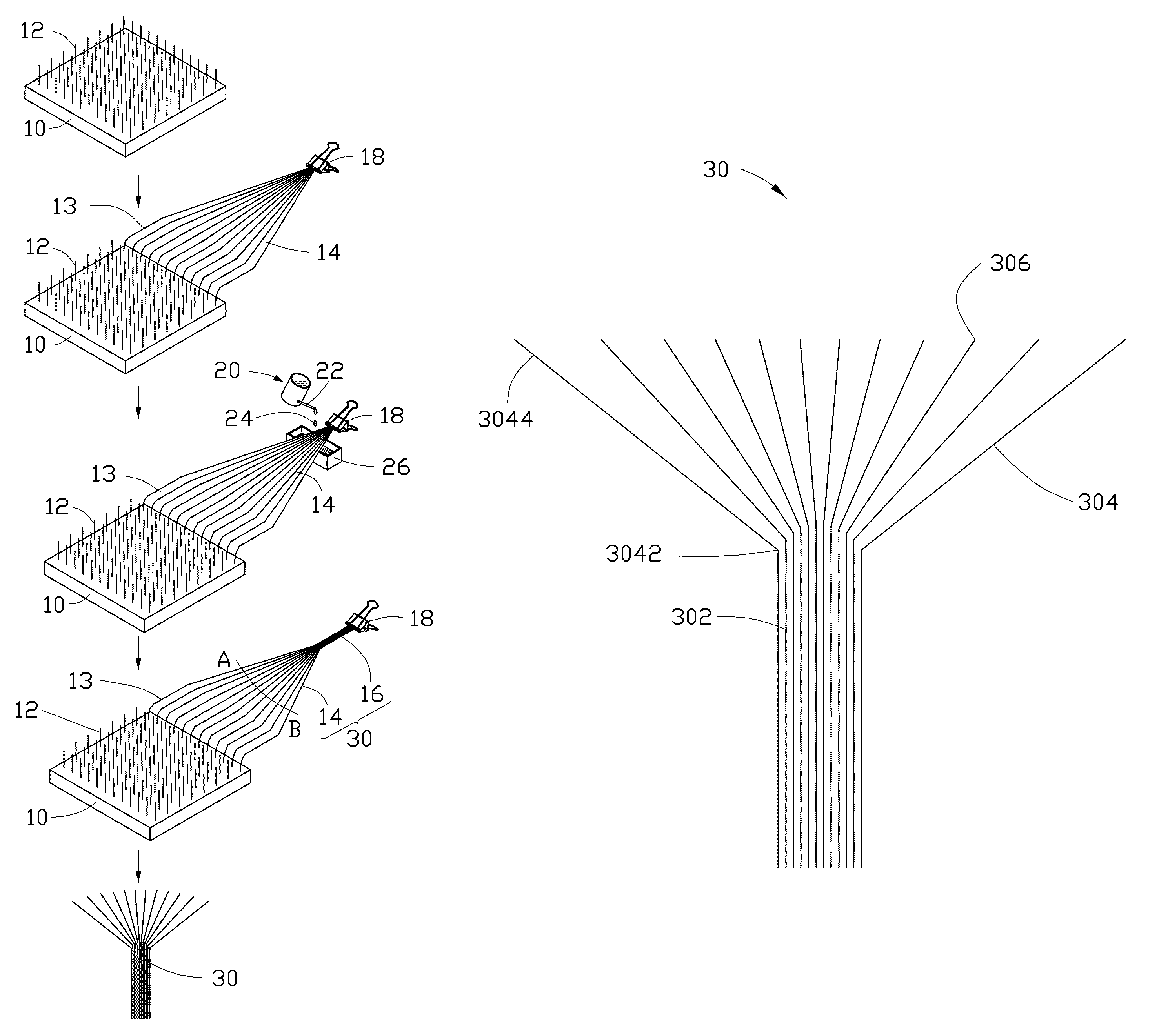
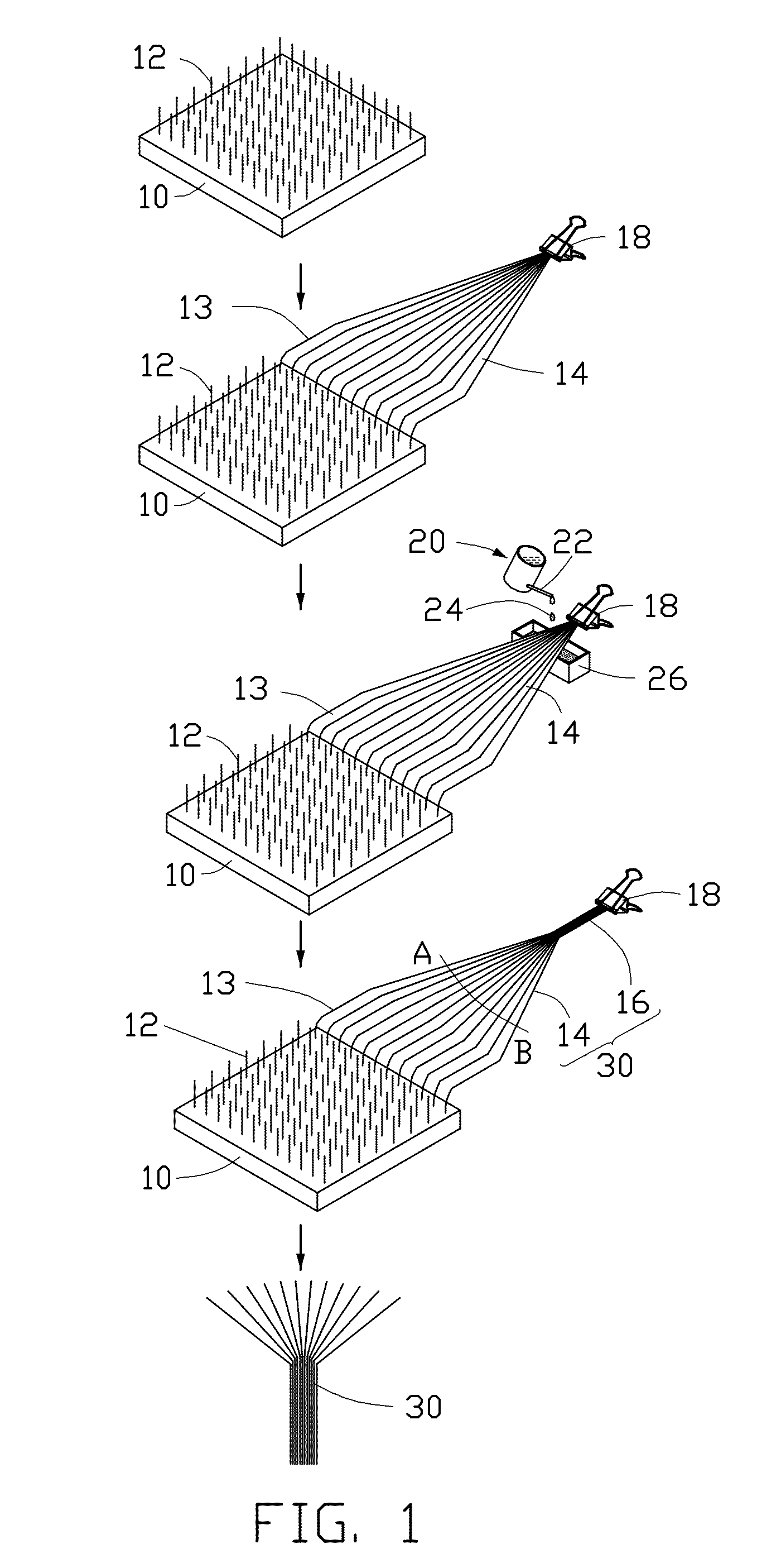
[0024]Referring to FIG. 1, a method for making a carbon nanotube field emitter 30 of the first embodiment includes following steps:

[0025]S1, providing a carbon nanotube array 12 located on a surface of a substrate 10;

[0026]S2, selecting some carbon nanotube segments of the carbon nanotube array 12 and pulling out a carbon nanotube film from the carbon nanotube array 12 by a drawing tool 18, wherein the carbon nanotube film includes a triangle region 14;

[0027]S3, treating a portion of the carbon nanotube film with an organic solvent 24 to form a carbon nanotube wire 16, wherein the carbon nanotube wire 16 includes a vertex of the triangle region 14;

[0028]S4, cutting off the triangle region 14 from the carbon nanotube film by a laser beam along a cutting line AB, wherein a distance between the vertex of the triangle region 14 and the cutting line AB can be in a range from about 10 microns to about 5 millimeters, to obtain a fan-shaped or triangular carbon nanotube field emitter 30.

[00...

second embodiment

[0057]While rotating the drawing tool 18, a pulling force is still applied on the carbon nanotube film, and the plurality of carbon nanotube segments is twisted. Further, by pulling the drawing tool 18, more and more carbon nanotubes can be drawn from the carbon nanotube array 12 to extend the length of the carbon nanotube film. In the second embodiment, the value of twist force is in a range from about 0.00005 Newton to about 0.001 Newton.

[0058]Referring to FIG. 5, it is to be understood, the carbon nanotube film can be separated from the carbon nanotube array 12. In the length direction, one end of the carbon nanotube film is supported by the support cylinder 15, and the other end is held by the drawing tool 18. The support cylinder 15 and the drawing tool 18 are simultaneously twisted along two reverse directions, to twist the portion of the carbon nanotube film into the carbon nanotube wire 16.

[0059]It is to be understood, the carbon nanotube wire 16 formed by twisting the porti...


PUM

PropertyMeasurementUnit
distanceaaaaaaaaaa
twist forceaaaaaaaaaa
distanceaaaaaaaaaa

Abstract

The present application relates to a method for making a carbon nanotube field emitter. A carbon nanotube film is drawn from the carbon nanotube array by a drawing tool. The carbon nanotube film includes a triangle region. A portion of the carbon nanotube film closed to the drawing tool is treated into a carbon nanotube wire including a vertex of the triangle region. The triangle region is cut from the carbon nanotube film by a laser beam along a cutting line. A distance between the vertex of the triangle region and the cutting line can be in a range from about 10 microns to about 5 millimeters.

Description

RELATED APPLICATIONS[0001]This application claims all benefits accruing under 35 U.S.C. §119 from China Patent Application No. 201210087168.1, filed on Mar. 29, 2012 in the China Intellectual Property Office, the disclosure of which is incorporated herein by reference.BACKGROUND[0002]1. Technical Field[0003]The present application relates to a method for making a field emitter, and particularly to a method for making a carbon nanotube based field emitter.[0004]2. Discussion of Related Art[0005]Many potential applications have been proposed for carbon nanotubes, including conductive and high-strength composites, energy storage and energy conversion devices, sensors, field emission displays, and nanometer-sized semiconductor devices.[0006]As the carbon nanotubes are used in field emitters, shielding effect between two adjacent carbon nanotubes makes only a few carbon nanotubes emit electrons. Therefore, an emission current density of the field emitter is very small. Improving an emiss...

Claims


Application Information

Patent Timeline
Patent Type & Authority Patents(United States)
IPC IPC(8): H01J9/02B82Y10/00B82Y99/00H01J9/04H01J9/12H01J1/304
CPCH01J9/025H01J2201/30469Y10S977/842H01J1/304B82Y99/00Y10S977/742B82Y10/00Y10S977/762Y10S977/939
Inventor LIU, PENGFAN, SHOU-SHAN
Owner TSINGHUA UNIV
Why Eureka
Try Eureka