Electro-optic displays, and processes for their production

a technology of optical displays and optical displays, applied in the field of optical displays, to achieve the effect of color displays

Active Publication Date: 2014-12-02
E INK CORPORATION
View PDF257 Cites 121 Cited by
  • Summary
  • Abstract
  • Description
  • Claims
  • Application Information

AI Technical Summary

Benefits of technology

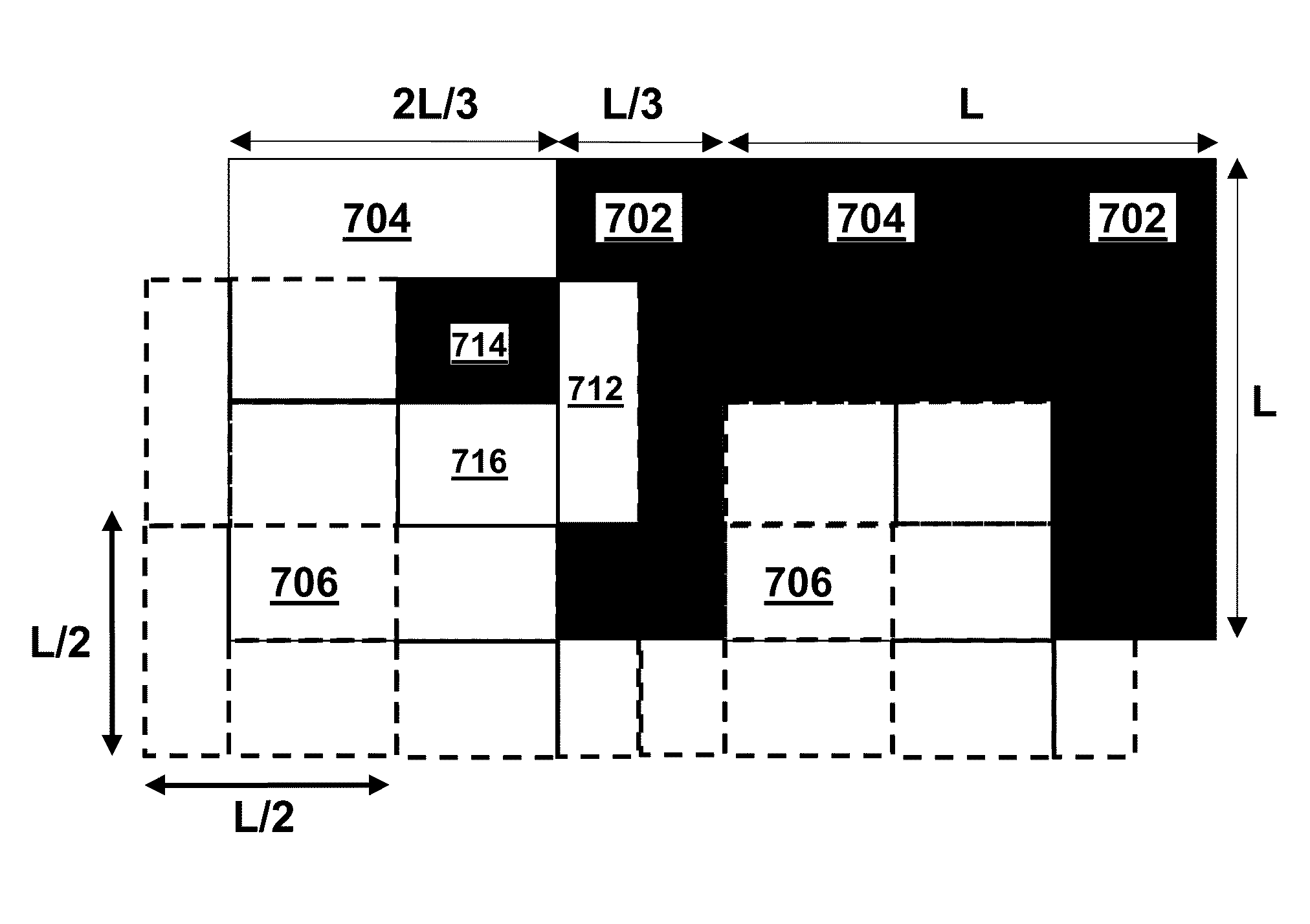
[0048]The color display of the present invention enable edge effects to be reduced, since each sub-pixel of a given color has two neighboring sub-pixels of the same color (for purposes of this application, two sub-pixels are regarding as neighboring when they share a common edge; sub-pixels which share only a corner are not regarded as neighboring), and (for reasons explained below) there are no edge effects between neighboring sub-pixels having the same color.

Problems solved by technology

Nevertheless, problems with the long-term image quality of these displays have prevented their widespread usage.
For example, particles that make up electrophoretic displays tend to settle, resulting in inadequate service-life for these displays.
Such gas-based electrophoretic media appear to be susceptible to the same types of problems due to particle settling as liquid-based electrophoretic media, when the media are used in an orientation which permits such settling, for example in a sign where the medium is disposed in a vertical plane.
Indeed, particle settling appears to be a more serious problem in gas-based electrophoretic media than in liquid-based ones, since the lower viscosity of gaseous suspending fluids as compared with liquid ones allows more rapid settling of the electrophoretic particles.
However, as already mentioned these prior art techniques are not satisfactory for forming, on arbitrary three-dimensional shapes, electrophoretic medium coatings with a sufficiently uniform thickness to give optimum optical performance.
While coating methods such as dip or spray coating can be applied to arbitrary three-dimensional shapes, it is difficult to or impossible to achieve uniform capsule monolayers over the substrate surface using these coating techniques.
Other problems encountered with slot coating techniques include:(a) chatter-like streaks parallel to the coating head (for example, due to vibrations in the coating apparatus); these streaks are believed to result from periodic bunching or jamming of capsules;(b) streaking in the direction of coating (i.e., perpendicular to the slot of the coating head), believed to be due to capsule jamming or non-uniform flows in delivery of capsules to the coating head;(c) less than desirable capsule contact (or wetting) with the optical face due to inadequate settling or deformability of the small capsules (of the order of 20-200 μm) typically used in encapsulated electrophoretic displays; and(d) non-uniformities in coating thickness due to formation of multiple layers of capsules (see the aforementioned U.S. Pat. No. 6,839,158 for a discussion of the advantages of forming only a single layer of capsules on a substrate).
The presence of these types of defects can adversely affect the appearance and optical performance of the display.
Also, as is well known to those skilled in slot coating technology, slot coating imposes limitations upon the viscosity and other physical properties of the material being coated, and typically requires the addition of slot coating additives to control the rheology of the coated material to ensure that the coating does not flow and develop non-uniformities in thickness prior to drying.
Although the binder serves several useful functions, including ensuring adequate adhesion of the capsule film to the substrate on which it is coated, excessive amounts of binder can hinder capsule contact with the electrode which is normally present on the substrate, and may also hinder the desirable flattening of the faces of the capsules in contact with the conductive coating (see, for example, the aforementioned U.S. Pat. No. 6,067,185).
Because the binder typically has a substantial effect on the viscosity and other physical properties of the capsule / binder mixture, at least in some cases it may be difficult to reduce the amount of binder used and still maintain these physical properties at values compatible with slot coating.
However, while conventional printing techniques might be used to prepare large displays of this type having resolutions of (say) less than 10 lines per inch (approximately 0.4 lines per mm), producing high resolution displays of this type with resolutions of about 100 lines per inch (approximately 4 lines per mm) with such conventional techniques is very difficult.
Again, while spray or ink jet coating might be used to apply the patterned coatings of capsules, producing monolayer capsule coatings using these methods will be difficult or impossible.
Switching between two colors (red plus blue, for example) is not possible in this type of display.
If the same backplane is used for an RGBW color display with the red, green, blue and white sub-pixels of each color pixel arranged in a 2×2 matrix, the resolution of the color display drops to 88 dpi (about 3.4 dots per mm), which is objectionable to many users who find the individual pixels readily visible.
As discussed in more detail below, in practice the sub-pixel edges are subject to certain edge effects which compromise the color rendering of the display by causing desaturation and darkening of the primary colors.
Such edge effects can cause serious adverse effects upon the color rendering properties of the display.

Method used


Image

  • Electro-optic displays, and processes for their production
  • Electro-optic displays, and processes for their production
  • Electro-optic displays, and processes for their production

Examples


Embodiment Construction

[0056]As already mentioned, U.S. Pat. No. 7,339,715 describes a process for forming a coating of an encapsulated electrophoretic medium on a substrate. In this process, there are dispersed in a fluid a plurality of capsules, each of which comprises a capsule wall, a fluid encapsulated within the capsule wall and a plurality of electrically charged particles disposed in the fluid and capable of moving therethrough on application of an electric field to the capsule. A conductive portion of a substrate is contacted with the fluid, and a potential difference is applied between this conductive portion of the substrate and a counter-electrode in electrical contact with the fluid. The application of this potential difference causes capsules to be deposited upon the conductive portion of the substrate. Thus, in this process the capsules are electrophoretically deposited on a predetermined portion of the substrate, and the process may hereinafter for convenience be referred to as the “electr...


PUM

PropertyMeasurementUnit
sizeaaaaaaaaaa
angleaaaaaaaaaa
widthsaaaaaaaaaa

Abstract

A color display has continuous areas of a single color covering a plurality of sub-pixel electrodes. Each sub-pixel of a given color has sub-pixels of the same given color disposed along at least two of its adjacent edges. Each area of a single color may cover a 2×2 array of sub-pixel electrodes. The colors used may be red / green / blue / white (RGBW), red / green / blue / yellow (RGBY), or orange / lime / purple / white.

Description

REFERENCE TO RELATED APPLICATIONS[0001]This application is a continuation-in-part of application Ser. No. 11 / 833,578, filed Aug. 3, 2007 (Publication No. 2008 / 0023332, now U.S. Pat. No. 7,910,175, issued Mar. 22, 2011).[0002]This application is also related to application Ser. No. 09 / 349,806, filed Jul. 8, 1999 (Publication No. 2002 / 0113770), now abandoned, and to application Ser. No. 10 / 817,464, filed Apr. 2, 2004 (Publication No. 2004 / 0190114, now U.S. Pat. No. 7,667,684, issued Feb. 23, 2010), which is a continuation of the aforementioned application Ser. No. 09 / 349,806. This application is also related to U.S. Pat. No. 7,339,715.[0003]The entire contents of the aforementioned applications, and of all other U.S. patents and published and copending applications mentioned below, are herein incorporated by reference.BACKGROUND OF INVENTION[0004]This invention relates to electro-optic displays, and processes for the production of such displays. Some of the processes of the invention ...

Claims


Application Information

Patent Timeline
Patent Type & Authority Patents(United States)
IPC IPC(8): G06K9/00G02B26/00G09G3/34H04N9/10G02F1/167
CPCG02F2201/52G02F1/167
Inventor BOUCHARD, ALAINWHITESIDES, THOMAS H.WALLS, MICHAEL D.DUDEK, STEVEN P.
Owner E INK CORPORATION
Why Eureka
Try Eureka