Modulation-forward error correction (MFEC) codes and methods of constructing and utilizing the same

a module-forward error correction and code technology, applied in the field of binary block transmission codes, can solve the problems of not addressing all or even a majority of the common transmission problems, error correction is applied in the direction of coding, digital transmission, code conversion,

Active Publication Date: 2014-12-02
ZEPHYR PHOTONICS
View PDF22 Cites 12 Cited by
  • Summary
  • Abstract
  • Description
  • Claims
  • Application Information

AI Technical Summary

Problems solved by technology

Now, however, error correction is being applied to scenarios where the probability of error is relatively low, such as communication between two servers, which are communicating through some parallel or serial connection, or any two communication devices on any suitable electrical backplane.
However, many of these correction codes and methods therewith do not address all, or even a majority, of the common transmission problems generally encountered.

Method used


Image

  • Modulation-forward error correction (MFEC) codes and methods of constructing and utilizing the same
  • Modulation-forward error correction (MFEC) codes and methods of constructing and utilizing the same
  • Modulation-forward error correction (MFEC) codes and methods of constructing and utilizing the same

Examples


first embodiment

[0085]FIG. 4 depicts an Encoding Processor in accordance with one embodiment of the present invention. As shown in the Figure, there are two embodiments that may be selected for processing the encoding of the Message. In a first embodiment, following the path down the left side of the Figure, each Message is processed using a Lookup Table 420, which contains the value of the codeword to which the Message is encoded. In such an embodiment, the inputs include the Message, including a control flag indicating whether the Message is a Data Message or a Control Message, such as a comma, as well as the present state indicator.

[0086]The present state indicator identifies the current disparity state of the transmission, and is updated according to the state machine, for example, as shown in FIG. 5. In a basic embodiment, the codewords are grouped into positive- and negative-disparity pairs. Thus, a decision is made during the Message encoding process, as to which of the pairs will be used as...

second embodiment

[0091]Returning to FIG. 4, in the second embodiment for processing the encoding of the Message, following a path down the right side of the Figure, each Message is processed by a computational encoder 430, as detailed in FIG. 6. The Computational Encoder may be advantageous and more efficient for larger codes, for which direct use of lookup encoding may be impractical or undesirable. Computational Encoding makes use of the underlying mathematical structure of the Base FEC Code. In such an embodiment, a first step is to use a Lookup Table 620 to process the Message 610, including a control flag and state identifier, to obtain a base FEC Message 630 that will be processed using methods available for the Base FEC Code, as shown in block 640.

[0092]In the exemplary embodiment, discussed supra, the Base FEC code is a cyclic Hamming code. This is a linear code, for which linear algebraic methods permit the computational conversion of a Base FEC Message to be encoded into a Base FEC Codewor...


PUM


Abstract

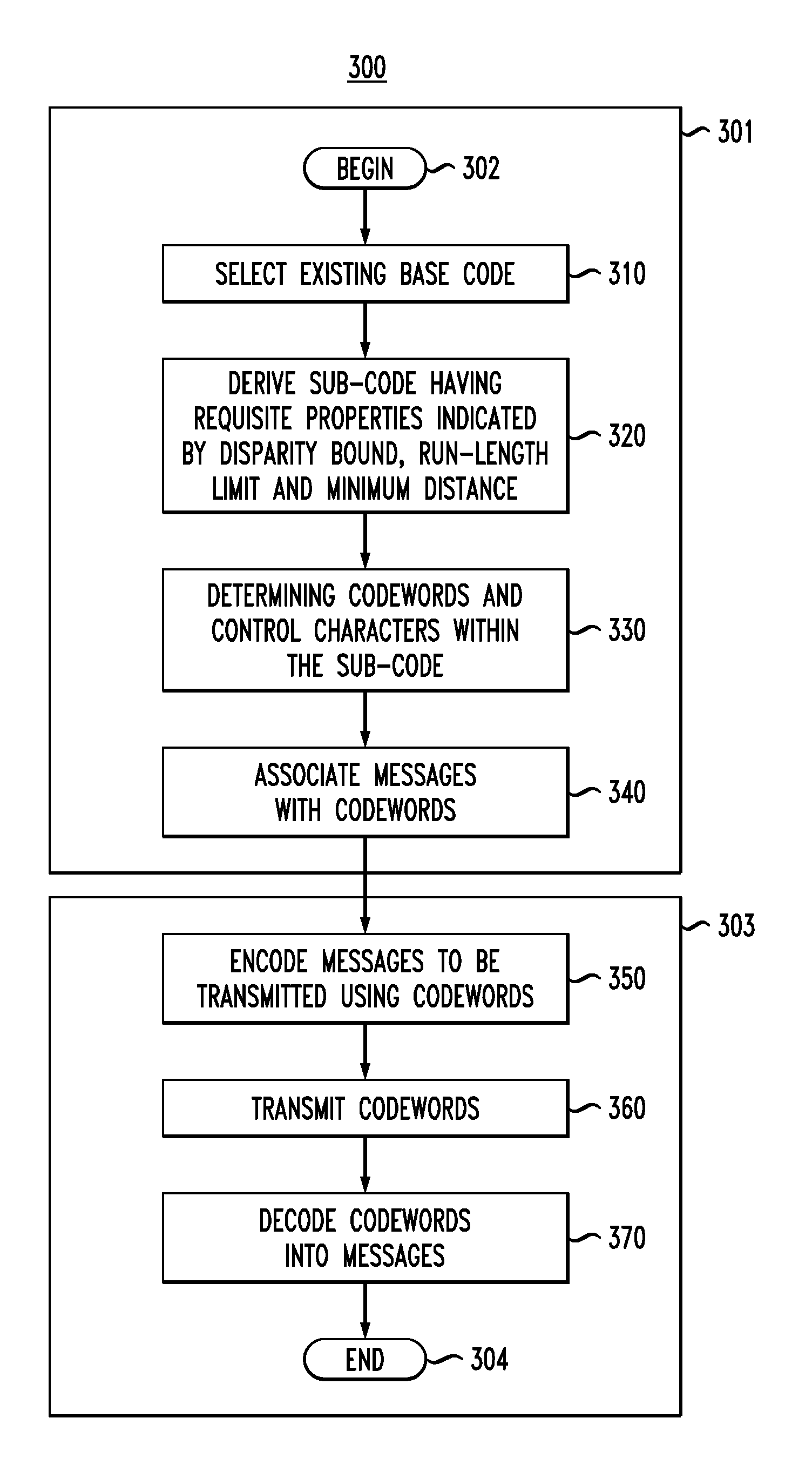
Embodiments of the present invention generally relate to binary block transmission codes for high-speed network transmissions. More specifically, embodiments of the present invention relate to bounded-disparity run-length-limited forward error correction codes and methods of constructing and utilizing same. In one embodiment, a method for generating binary block bounded-disparity run-length-limited forward error correction transmission codes comprises selecting an existing base code, deriving a sub-code from the existing base code, having properties indicated by disparity bound, run-length limit and minimum distance, ascertaining a plurality of codewords and control characters from within the sub-code, encoding Messages to be transmitted with at least one codeword from the plurality of codewords, transmitting codewords from a transmitter to a receiver, and decoding the codewords into Messages.

Description

BACKGROUND[0001]1. Field of the Invention[0002]Embodiments of the present invention generally relate to binary block transmission codes for high-speed network transmissions. More specifically, embodiments of the present invention relate to forward error correction codes that are simultaneously bounded-disparity and / or run-length-limited and methods of constructing same.[0003]2. Description of the Related Art[0004]Error correction was once reserved for scenarios where probability of error was high, such as communication between two wireless devices. Now, however, error correction is being applied to scenarios where the probability of error is relatively low, such as communication between two servers, which are communicating through some parallel or serial connection, or any two communication devices on any suitable electrical backplane.[0005]Many known error correction techniques are performed by using correction codes to transform error data into useable, and highly reliable, bytes ...

Claims


Application Information

Patent Timeline
Patent Type & Authority Patents(United States)
IPC IPC(8): H03M13/03H03M7/46
CPCH03M5/145H03M13/31H04L1/0058
Inventor STARK, JASON BLAIN
Owner ZEPHYR PHOTONICS
Why Eureka
Try Eureka