Optical lens having sub-wavelength structure containing aluminum or aluminum oxide, method of manufacturing optical lens, and imaging optical system including optical lens

a technology of optical lenses and aluminum oxides, applied in the field of optical elements, can solve the problems of affecting the function and appearance of coatings during long-term use, affecting the efficiency of optically ineffective areas, and increasing the load on coatings, so as to improve heat resistance and flexibility

Inactive Publication Date: 2014-12-09
CANON KK
View PDF11 Cites 6 Cited by
  • Summary
  • Abstract
  • Description
  • Claims
  • Application Information

AI Technical Summary

Benefits of technology

[0014]According to the present invention, the following element can be provided: an optical element including an optically ineffective area partly or entirely coated with a coating which contains a cured product having improved heat resistance and flexibility and which is opaque at wavelengths used.
[0015]According to the present invention, the optical element includes the optically ineffective area partly or entirely coated with the opaque coating and therefore is effective in a high-temperature process or high-temperature, high-humidity process used to form another coating on an optically effective area.

Problems solved by technology

In the case of installing a plurality of lenses such as camera lenses in a lens barrel, although the lenses individually serve as optically effective areas, some of the lenses are likely to serve as optically ineffective areas because no light passes therethrough depending on the sizes and positions of other lenses.
This increases the load on the coatings to negatively affect the function and appearance of the coatings during long-term use.
These phenomena suggest the cured product is degraded and is reduced in flexibility by thermal decomposition and oxidation.
Thermal decomposition and oxidation possibly cause phenomena such as the formation of cracks and / or voids in actual opaque coatings and the removal of the coatings from bases of optical elements by thermal stress.
Usually, these phenomena result in the whitening of appearance and the easiness of moisture penetration.

Method used


Image

  • Optical lens having sub-wavelength structure containing aluminum or aluminum oxide, method of manufacturing optical lens, and imaging optical system including optical lens
  • Optical lens having sub-wavelength structure containing aluminum or aluminum oxide, method of manufacturing optical lens, and imaging optical system including optical lens
  • Optical lens having sub-wavelength structure containing aluminum or aluminum oxide, method of manufacturing optical lens, and imaging optical system including optical lens

Examples


example 1

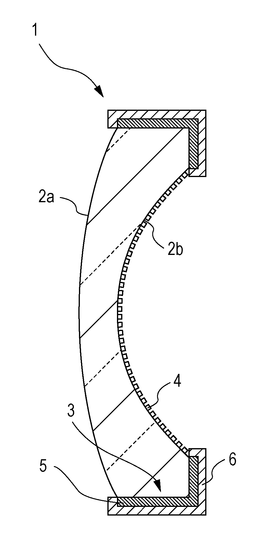
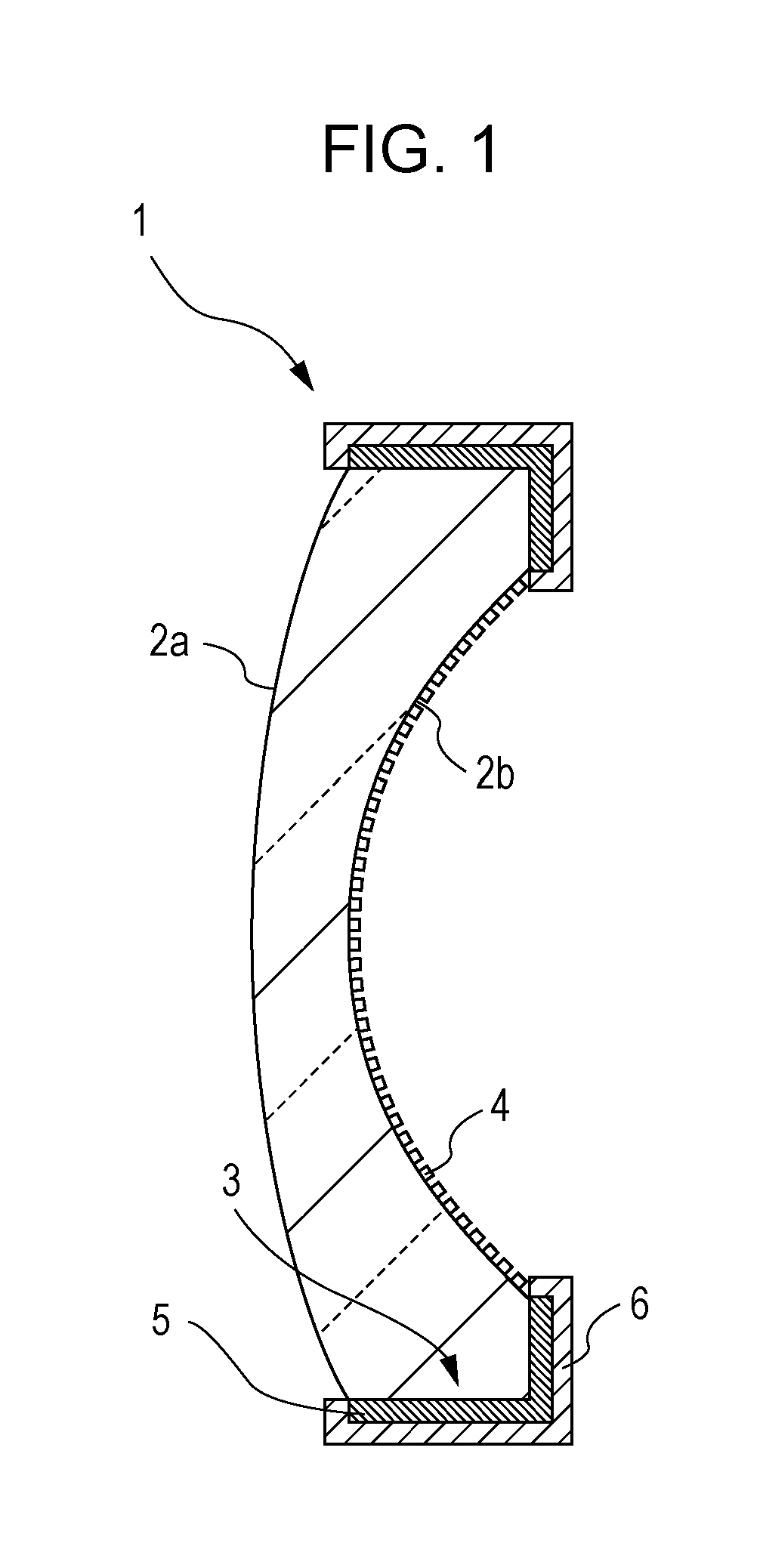
[0044]FIG. 1 is a sectional view of an optical element, including an optically ineffective area coated with an opaque coating, according to an embodiment of the present invention. With reference to FIG. 1, reference numeral 1 represents the optical element, reference numerals 2a and 2b represent optically effective areas, reference numeral 3 represents the optically ineffective area, and reference numeral 5 represents the opaque coating. The optical element 1 is shown in the form of a lens. The opaque coating 5 is disposed on the optically ineffective area 3. The thickness of the opaque coating 5 is shown in an enlarged scale in FIG. 1 for ease of illustration.

[0045]In this example, a coating material for forming the opaque coating 5 was prepared by mixing eight parts by weight of a base compound, prepared by mixing an epoxy resin with an additive such as a black dye, available from Canon Chemicals Inc. under the trade name GT-7A; 1.26 parts by weight of a bisphenol-A epoxy resin, u...

example 2

[0050]An optical element including an optically effective area having a sub-wavelength structure disposed thereon and an optically ineffective area coated with an opaque coating was manufactured in substantially the same manner as that described in EXAMPLE 1 except that a coating material containing a phenol resin was not applied to the opaque coating and therefore a protective coating was not formed after the opaque coating was formed.

[0051]The optical element was subjected to substantially the same high-temperature, high-humidity reliability test as that described in EXAMPLE 1. The observation of the appearance of the resulting optical element showed that the opaque coating on the optically ineffective area had no change as compared to the untested opaque coating, was good, and had no functional problem.

example 3

[0052]An optical element including an optically effective area having a sub-wavelength structure disposed thereon and an optically ineffective area coated with an opaque coating was manufactured in substantially the same manner as that described in EXAMPLE 1 except that a coating material containing a particulate component with a small particle size of 1 μm or less and a base compound prepared by mixing a commercially available black dye with an additive was used.

[0053]The optical element was subjected to substantially the same high-temperature, high-humidity reliability test as that described in EXAMPLE 1. The observation of the appearance of the resulting optical element showed that the opaque coating on the optically ineffective area had no change as compared to the untested opaque coating, was good, and had no functional problem.


PUM

PropertyMeasurementUnit
temperatureaaaaaaaaaa

Abstract

An optical element includes an optically effective area and an optically ineffective area partly or entirely coated with a coating opaque at wavelengths used. The opaque coating contains a cured product prepared from an epoxy resin and a curing agent containing an alicyclic acid anhydride. The alicyclic acid anhydride is preferably methylhexahydrophthalic anhydride or hexahydrophthalic anhydride.

Description

BACKGROUND OF THE INVENTION[0001]1. Field of the Invention[0002]The present invention relates to optical elements and particularly relates to an optical element suppressing the generation of harmful light causing flares or ghosts.[0003]2. Description of the Related Art[0004]For optical elements such as lenses, various techniques have been proposed for the purpose of suppressing the generation of harmful light that causes flares or ghosts to obtain high-quality, high-performance optical systems. The techniques are classified into two: (1) a technique for reducing reflection by increasing the light transmittance of an optically effective area and (2) a technique for reducing reflection by increasing the light absorbance of an optically ineffective area.[0005]The term “optically effective area” as used herein refers to an area through which light passes. The term “optically ineffective area” as used herein refers to an area through which no light passes. In the case of installing a plu...

Claims


Application Information

Patent Timeline
Patent Type & Authority Patents(United States)
IPC IPC(8): G02B27/00B29D11/00G02B1/11G02B5/00G02B1/118G02B3/00
CPCG02B5/003B29D11/00903G02B1/118
Inventor KAWAUCHI, HIROSHIYAMADA, MASAYUKIOKUNO, TAKEHARUOGAWA, RYONAKAYAMA, TOMONARI
Owner CANON KK
Why Eureka
Try Eureka