Photoelectric conversion element

a technology of conversion elements and photoelectrics, applied in the direction of light-sensitive devices, electrically conductive capacitors, solid-state devices, etc., to achieve the effects of high practical use, improved design properties of elements, and high conversion efficiency and stability

Active Publication Date: 2014-12-09
DAI ICHI KOGYO SEIYAKU CO LTD
View PDF4 Cites 4 Cited by
  • Summary
  • Abstract
  • Description
  • Claims
  • Application Information

AI Technical Summary

Benefits of technology

[0030]The photoelectric conversion element of the present invention has photoelectric conversion efficiency and stability comparable to the element using the iodine redox couple of the related art, and is a photoelectric conversion element which solves the problems of transparency which was a weak point of the iodine redox couple of the related art. In detail, since the redox couple used in the present invention does not have strong absorption property in a visible light area, a design property of the element is improved, and since the ionic liquid having a low volatile property is dissolved in high concentration, even in a case of using the ionic liquid as a solvent, degradation in element performance due to light absorption of the electrolyte layer shown in the iodine redox couple does not occur, and thus, it is possible to provide a photoelectric conversion element of high practical use.

Problems solved by technology

However, since a sublimation property of iodine is high, element sealing is difficult and it causes a decrease of element durability under high temperature conditions.
In addition, since iodine has a high corrosive property with respect to a lot of metals, metals which can be used in an element substrate are limited, and an expensive substrate such as conductive glass is necessary to be used.
Further, in a case of an element, particularly with a large area, metal power collecting lines are provided on the substrate for high performance, in many cases, however, as in this case, it is necessary to provide a process of preventing contact of the electrolyte and the power collecting lines for preventing corrosion of the metal power collecting lines, operating steps are complicated, and an effective area of the element is decreased.
Further, the iodine redox couple has a strong absorbing property in a visible light area, and in a case of using a solvent with high viscosity such as ionic liquid, it is necessary to increase a concentration of the iodine redox couple to be sufficiently operated as a solar cell element, and accordingly, light absorption of a dye is disturbed and it becomes a reason for performance degradation.
In addition, in a case of emphasizing a colorful property of the solar cell using various dyes, particularly in a case of a blue element, the color of iodine becomes impeditive, and thus it is not suitable in a viewpoint of element design.
As described above, the iodine redox couple has high performance as the redox couple, however, since it also has problems, a redox couple which can be replaced with the iodine redox couple is required, and there have been some investigation into the matter (for example, see NPL 1 to 6 and PTL 1).
The cobalt complex shows the same performance as the iodine redox couple under weak optical conditions, however, since it has a large molecular size, a moving speed of the redox couple is slow, and the performance is degraded by half under pseudo solar light irradiation conditions.
In addition, the cobalt complex is expensive compared to the iodine redox couple, and it cannot be said to be used practically.
(SeCN)2 / SeCN− shows high performance compared thereto, however, has problem in safety, and it cannot be said to be used practically.
As redox couples which can be used for the photoelectric conversion element other than the iodine redox couple, Br2 / Br−, Fe(CN)64− / Fe(CN)63−, Fe2+ / Fe3+, S2− / Sn2−, Se2− / Sen2−, V2+ / V3+, quinone / hydroquinone, and the like are used, however, there are problems in performance, stability, safety, and the like, and the performance comparable to the iodine redox couple has not been obtained.
However, in a case of using a volatile organic solvent such as acetonitrile or ethylene carbonate shown in NPL 6, as an electrolyte of the dye-sensitized solar cell, enclosure of the electrolyte is difficult and practical element durability is difficult to be obtained.
Accordingly, there are many examples of using ionic liquid having significantly low volatile property as the electrolyte solvent, however, since the ionic liquid has higher viscosity than the general volatile organic solvent, as shown in PTL 1, there is a problem in that the element performance is lower than the organic solvent electrolyte.
In addition, NPL 6 shows a case of using tetramethylammonium salts of the sulfide compound as a reductant of the redox couple, however, in this case, there are problems in that solubility to the ionic liquid is insufficient and satisfied element performance is not exhibited.
In addition, PTL 1 shows a sulfide compound including a thiadiazole skeleton as the redox couple, however, there are problems in that a disulfide compound which is an oxidant of the redox couple particularly has low solubility to the electrolyte solvent such as the ionic liquid (less than 0.2 M), and at the time of using a solvent with high viscosity and low volatile property such as ionic liquid or the like, element performance is degraded.
Further, in a case where the concentration of the redox couple is set to be high, there is a problem in that the stability of the redox itself is degraded.

Method used


Image

  • Photoelectric conversion element
  • Photoelectric conversion element
  • Photoelectric conversion element

Examples


example 1

Production of Porous Metal Oxide Semiconductor

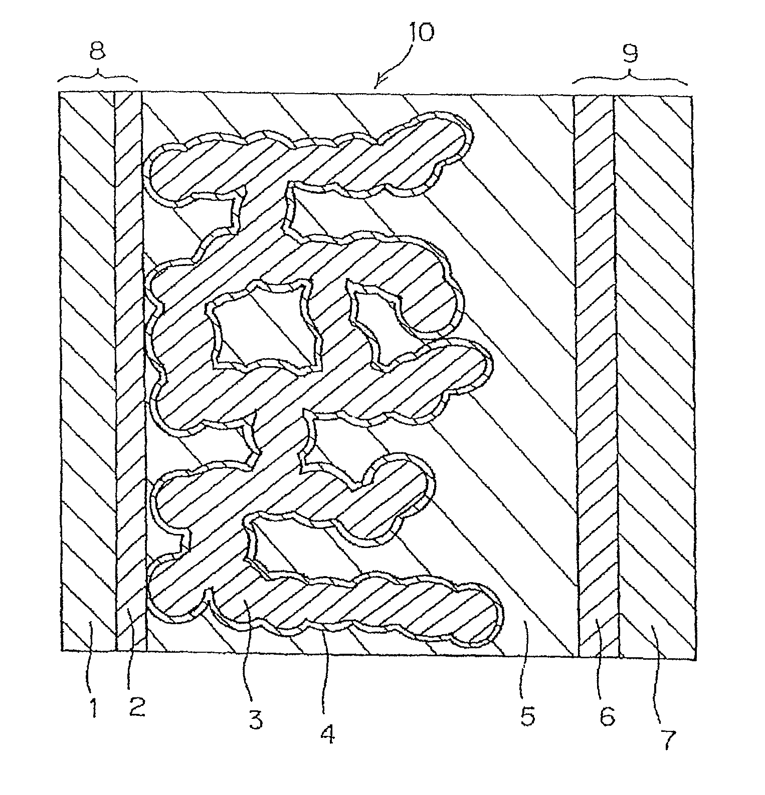
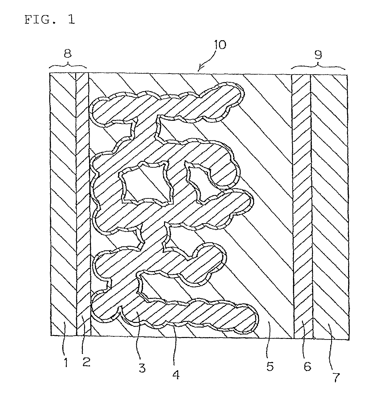
[0118]The porous metal oxide semiconductor layer 3 is formed on the transparent conductive film 2 which is formed of SnO2 obtained by doping fluorine on the transparent substrate 1 formed of glass and which is formed by vacuum deposition, by the following method.

[0119]As the electrode base material 8 in which the transparent conductive film 2 is formed on the transparent substrate 1, using FTO glass (manufactured by Nippon Sheet Glass Co., Ltd.), commercially available titanium oxide paste (product name: TSP-18NR, particle size of 20 nm manufactured by JGC Catalysts and chemicals, Ltd.) was printed on the surface thereof in a transparent conductive film 2 side, to have a film thickness of about 6 μm and an area of about 5 mm×10 mm by the screen printing method, commercially available titanium oxide paste (product name: TSP-400C, particle size of 400 nm manufactured by JGC Catalysts and chemicals, Ltd.) was further coated on the same area...

example 2

[0128]A solar cell element was produced in the same manner as in Example 1, except for using 1-methyl-5-mercapto-1,2,3,4-tetrazole: 1-methyl-1-propyl pyrrolidinium salt (MPPy-MTZT) instead of 1-methyl-5-mercapto-1,2,3,4-tetrazole: 1-methyl-3-ethylimidazolium salt (EMIm-MTZT) as the electrolyte layer 5.

example 3

[0129]A solar cell element was produced in the same manner as in Example 1, except for using 1-methyl-5-mercapto-1,2,3,4-tetrazole: 1,2-dimethyl-3-propyl imidazolium salt (DMPIm-MTZT) instead of 1-methyl-5-mercapto-1,2,3,4-tetrazole: 1-methyl-3-ethylimidazolium salt (EMIm-MTZT) as the electrolyte layer 5.


PUM


Abstract

Disclosed is a photoelectric conversion element which includes a semiconductor electrode, an opposite electrode, and an electrolyte layer held between the semiconductor electrode and the opposite electrode, and which is a photoelectric conversion element of high practical use using a redox couple which has high transparency and ease of enclosure and exhibits high performance compared to an iodine redox couple. An electrolyte layer includes a redox couple formed of compounds represented by General Formula (1) and Formula (2), and ionic liquid having bis(fluorosulfonyl)imide anion represented by Formula (3).

Description

TECHNICAL FIELD[0001]The present invention relates to a photoelectric conversion element which is suitably used as a dye-sensitized solar cell or the like.BACKGROUND ART[0002]In recent years, various solar cells have been proposed as a photoelectric conversion element which converts light energy into electrical energy. Among them, a dye-sensitized solar cell which is described in “Nature” 1991, 353, p. 737-740 or the like by Gratzel et. al. of Ecole Polytechnique de Lausanne in Switzerland in 1991 is used with low cost for materials and processes to be used, and thus, the practical use thereof is expected as the solar cell with low cost.[0003]In general, the dye-sensitized solar cell is configured with a semiconductor electrode which includes a photoelectric conversion layer which is formed of a semiconductor which has adsorbed a dye on a conductive base material, an opposite electrode which is provided with a catalyst layer on a conductive base material opposite to the semiconducto...

Claims


Application Information

Patent Timeline
Patent Type & Authority Patents(United States)
IPC IPC(8): H01L51/46H01G9/20
CPCH01G9/2059Y02E10/542H01G9/2013H01G9/2031Y02E10/52H01G9/2018H01L31/04
Inventor SAITO, YASUTERU
Owner DAI ICHI KOGYO SEIYAKU CO LTD
Why Eureka
Try Eureka