Multiphase soft-switched DC-DC converter

a dc-dc converter and multi-phase technology, applied in the direction of power conversion systems, electric variable regulation, instruments, etc., can solve the problems of large switching losses in semiconductor switches, and the need for larger output filters

Active Publication Date: 2014-12-09
APS ELECTRONICS
View PDF14 Cites 11 Cited by
  • Summary
  • Abstract
  • Description
  • Claims
  • Application Information

AI Technical Summary

Benefits of technology

[0020]Another advantage of the present invention, in the embodiments which make use of transformers, is that the voltage required for the commutation of the transformer currents is only a small fraction of the operating voltage of the circuit. As a result, much smaller components may be used, for example in high voltage applications, as the switching components are only required to work at this lower additional commutation voltage.
[0021]A further advantage of the invention is that the switching on and off of the load current in the diodes on the output side of the circuit occurs at a known, constant rate.

Problems solved by technology

In these circuits a dead time was created during the energy transfer (discontinuous energy transfer) which resulted in the need for larger output filters.
However, as frequency increases, so switching losses in semiconductor switches start to increase significantly, due to the finite switching speed or the time required for the current in the semiconductor device to start and stop flowing.
However, such quasi-resonant converter circuits still require relatively large capacitors for storing the amounts of charge necessary, and at the operating voltage.
Switching timing is also critical, which means that the control of the circuit operation is a non-trivial task, and may require a relatively complex design, or very low tolerance (ie expensive) resonance components and care over modelling parasitic.
If the circuit is switched sub-optimally, or not correctly matched to the resonant components, then switching losses and inefficiency can result.
This converter circuit, however, still requires a relatively large input capacitor to cope with the voltage swings across it and a relatively complicated control unit to generate the required pulse-width modulation and interleaved soft-switching timing in the primary and secondary switches.

Method used


Image

  • Multiphase soft-switched DC-DC converter
  • Multiphase soft-switched DC-DC converter
  • Multiphase soft-switched DC-DC converter

Examples


Embodiment Construction

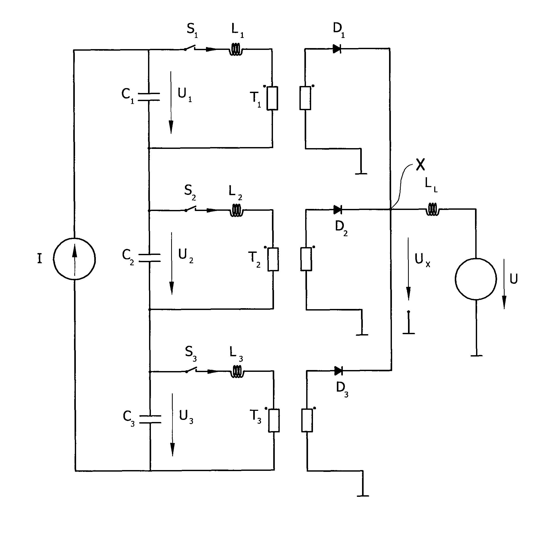
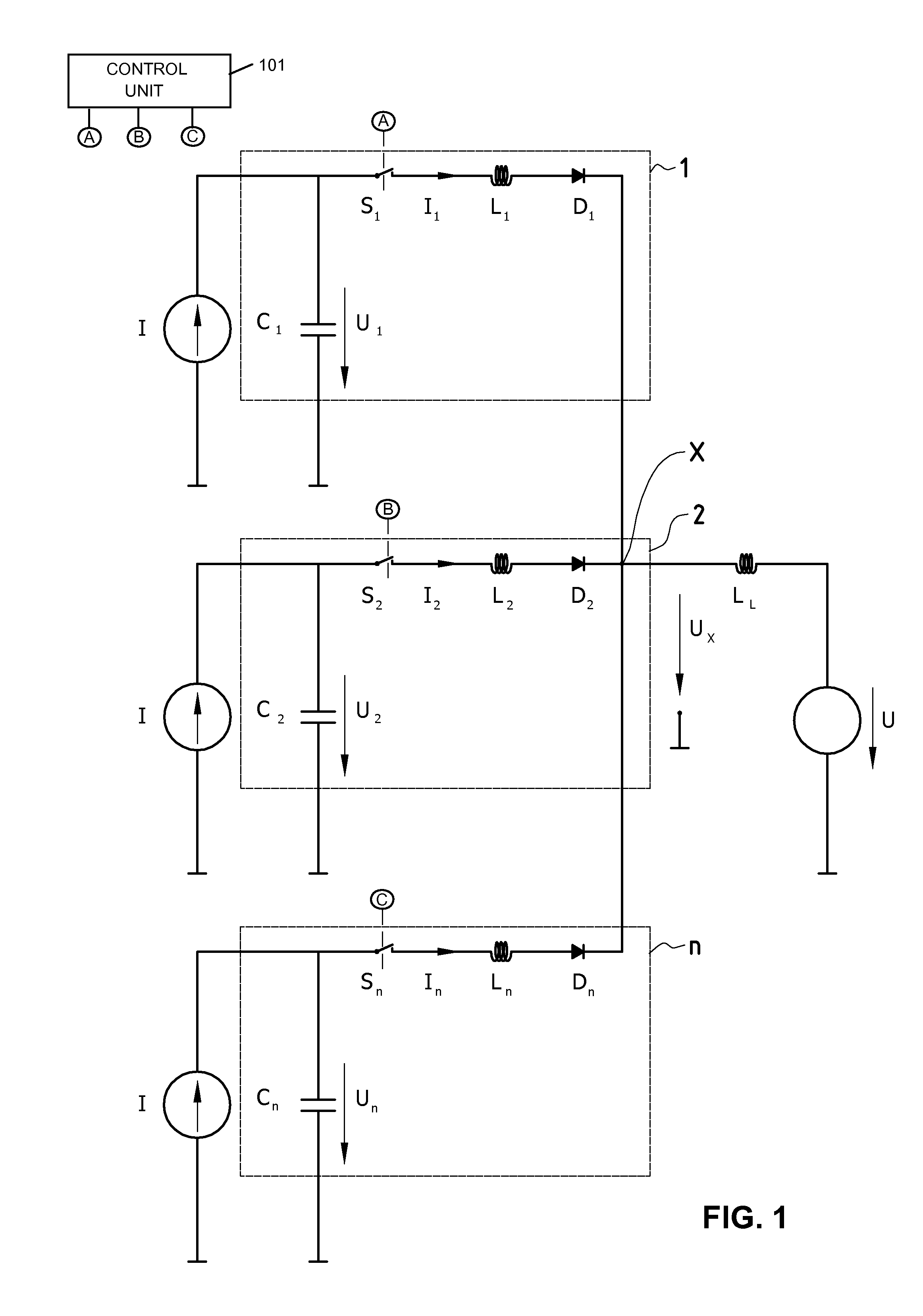
[0034]FIG. 1 illustrates a simplified abstraction of the principle behind the present invention. The circuit shows three converter circuits (1, 2, n) connected to a common load circuit. Each converter circuit comprises a capacitor (C1, C2, Cn), a switch (S1, S2, Sn), an inductance (L1, L2, Ln) and an output diode (D1, D2, DO. The voltages across the capacitors are U1, U2 and Un respectively. A control unit 101 controls the operation of the switch (S1 , S2, Sn) in each converter circuit (1, 2, n).

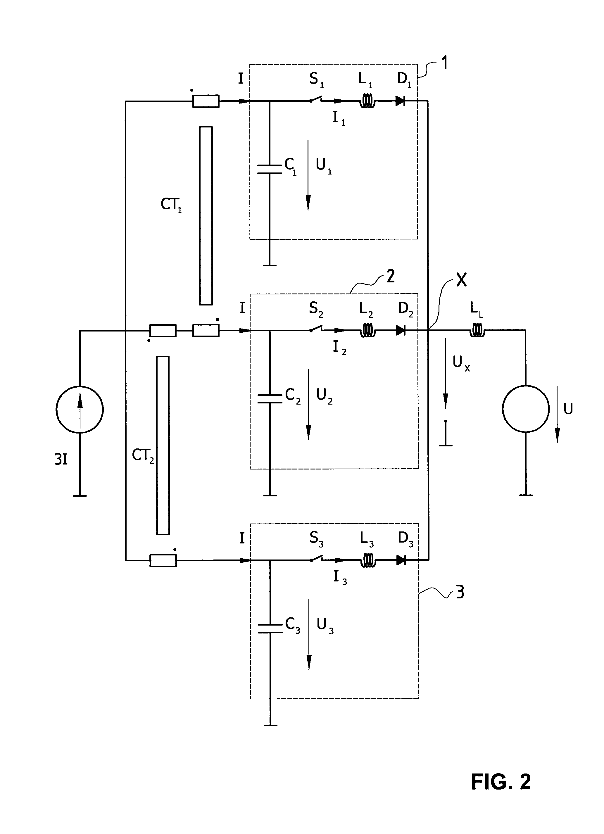
[0035]The circuit of FIG. 1 shows each converter circuit having a separate ideal current source I, however it will be understood that they may equally share a common current source. Such an arrangement is shown in FIG. 2, which shows three converter circuits sharing one ideal current source (3I) by means of two ideal current transformers (CT1, CT2) to form three ideal current sources (I). In the general case, with n converter circuits in parallel, (n−1) ideal current transformers would be re...


PUM


Abstract

A high-frequency DC to DC converter comprising n transient converter circuits (1, 2 . . . n) operating in parallel. The converter has constant transfer characteristics, and the transient converter circuits are operated phase-shifted by 360° / n and with interleaved duty cycles, which results in a continuous energy transfer through the circuit. The circuit is also soft-switched, with very low switching losses. In particular, the active semiconductors only switch off a relatively small magnetization current, during a recovery phase which can last as long as (n−1) / n of the switching phase period.

Description

BACKGROUND OF THE INVENTION[0001]1. Field of the Invention[0002]The invention relates to the field of high-frequency DC-DC converters in which electrical power at a first voltage is transferred from a power source to a load at a second voltage by high-frequency switching of current through circuits containing inductive and other resonant components. In particular, the invention relates to a family of multiphase converters in which two or more converter circuit slices are used to transfer electrical energy in parallel by switching current through the circuits sequentially in packets of energy.[0003]2. Description of the Related Art[0004]A DC-to-DC converter is a circuit which converts a direct current voltage at one level to a direct current voltage at another level. One of the primary design goals in such DC-to-DC converters is to increase the amount of power transferred through the converter. Common prior art DC-to-DC converter topologies include the buck or forward converter, the ...

Claims


Application Information

Patent Timeline
Patent Type & Authority Patents(United States)
IPC IPC(8): H02M3/335H02M3/337H02M1/00H02M3/158
CPCH02M2001/0074H02M2003/1586H02M3/3378H02M3/33538H02M3/337H02M3/1584H02M1/0074H02M3/1586H02M3/33573H02M3/33571H02M3/01
Inventor HILTBRUNNER, MAXCHRISTEN, URSRINIKER, HANS-RUDOLF
Owner APS ELECTRONICS
Why Eureka
Try Eureka