Imaging apparatus

a technology of imaging apparatus and carrier frequency, which is applied in the field of imaging apparatus, can solve the problems of insufficient carrier frequency intensity in imaging apparatus using the conventional two-dimensional talbot interference method, and the difficulty of the detector to detect interference patterns, etc., and achieve the effect of increasing the carrier frequency intensity

Inactive Publication Date: 2014-12-09
CANON KK
View PDF4 Cites 25 Cited by
  • Summary
  • Abstract
  • Description
  • Claims
  • Application Information

AI Technical Summary

Problems solved by technology

However, depending on a size of pitch of an interference pattern or a resolution of a detector, it may be difficult for the detector to detect the interference pattern.
However, the intensity of the carrier frequency is not sufficient in an imaging apparatus using the conventional two-dimensional Talbot interference method.

Method used


Image

  • Imaging apparatus
  • Imaging apparatus
  • Imaging apparatus

Examples


Embodiment Construction

[0027]Various exemplary embodiments, features, and aspects of the invention will be described in detail below with reference to the drawings.

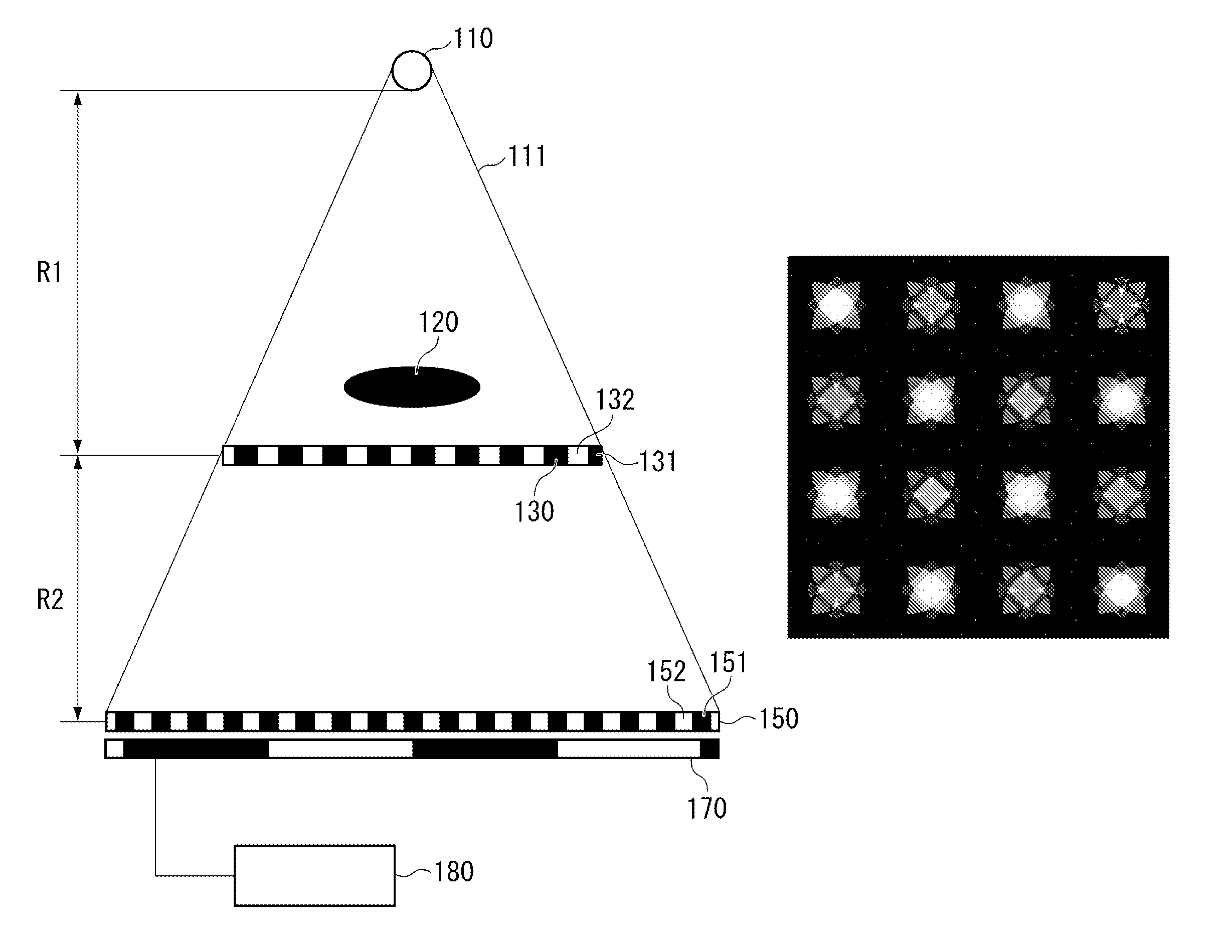
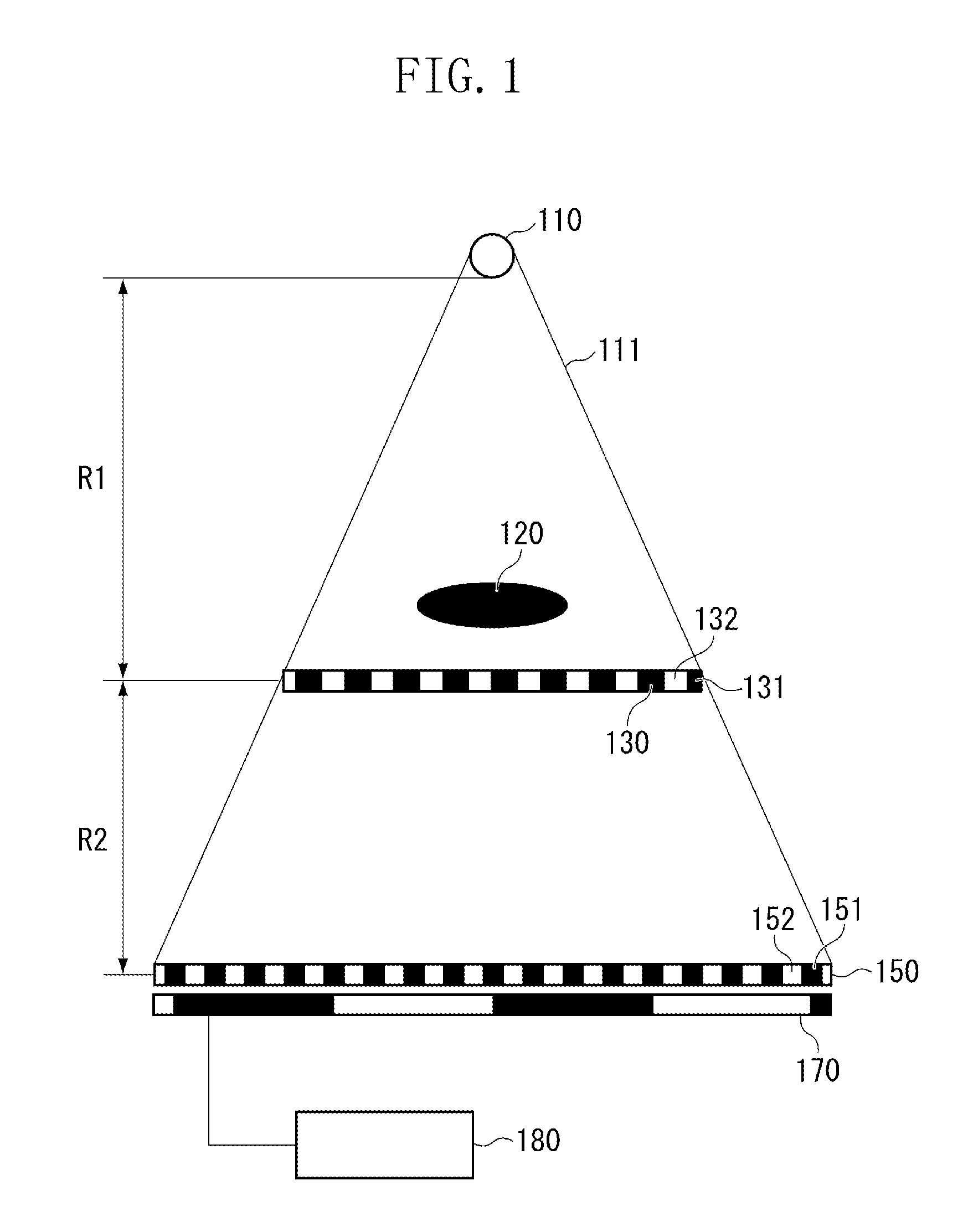
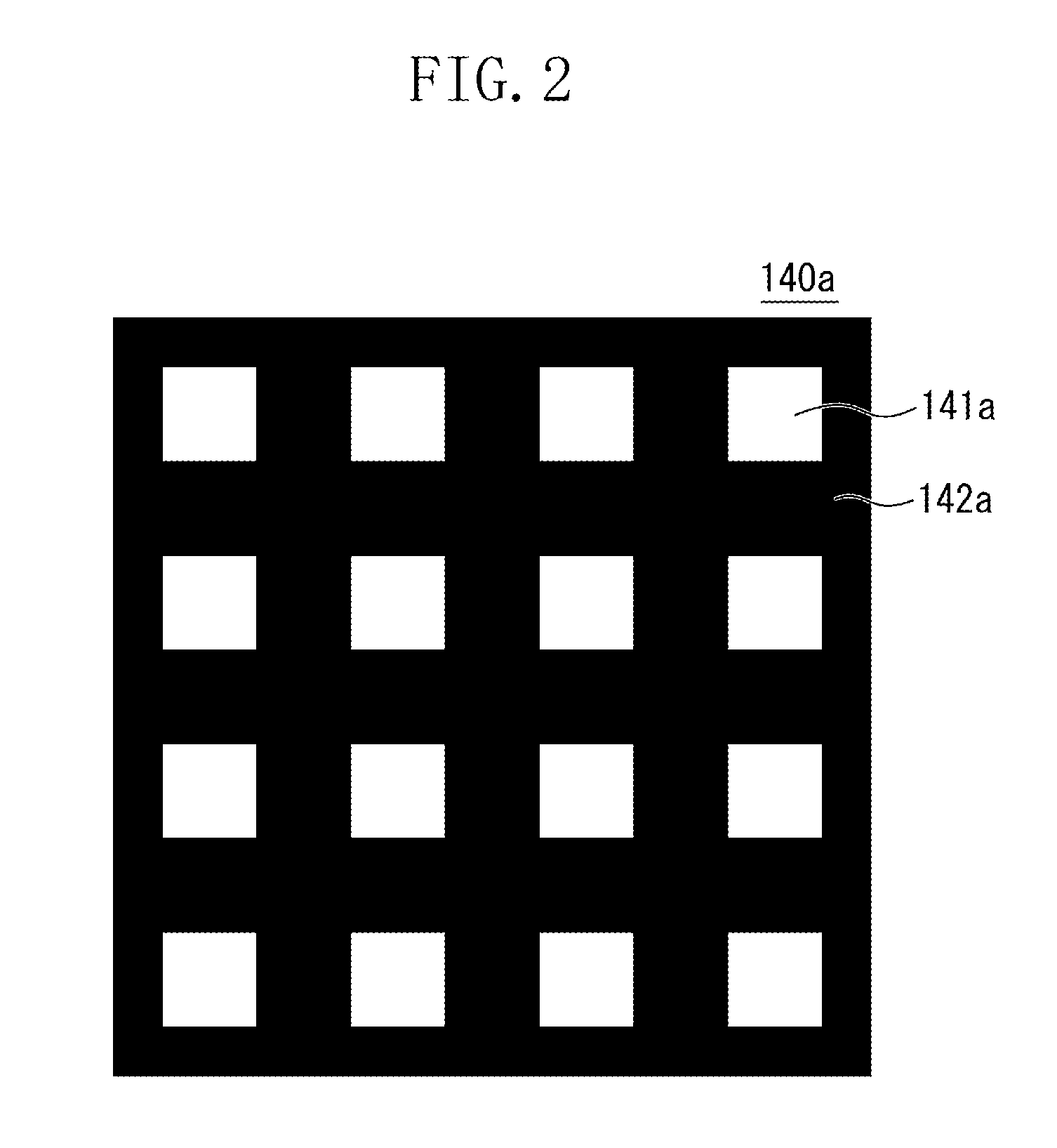
[0028]The inventors of the present invention discussed a shape and a size of the transmission portion of the shield grating for applying the two-dimensional Talbot interference method. As a result, it is possible to make the intensity of the carrier frequency of a moire greater than that in the past. The Talbot interference method in which a two-dimensional interference pattern is formed and a two-dimensional shield grating is used will herein be referred to as the two-dimensional Talbot interference method.

[0029]An exemplary embodiment of the present invention will be described in detail based on the appended drawings. The same reference numerals are attached to the same members in each figure and a duplicate description will not be repeated. In the present exemplary embodiment, an imaging apparatus applying the Talbot interference method usin...


PUM


Abstract

An imaging apparatus includes, a diffraction grating that diffracts an electromagnetic wave emitted from an electromagnetic wave source, a shield grating including a shield portion that prevents transmission of the electromagnetic wave and a plurality of transmission portions that allows the electromagnetic wave to transmit therethrough, and a detector that detects the electromagnetic wave transmitted through the transmission portions of the shield grating. The diffraction grating forms an interference pattern in a grid pattern by diffracting the electromagnetic wave; the shield grating has the plurality of transmission portions arranged two-dimensionally; and a ratio of an area of the transmission portion to the area of a unit pattern composed of a portion of the shield portion and one transmission portion of the plurality of transmission portions is larger than 0.25.

Description

BACKGROUND OF THE INVENTION[0001]1. Field of the Invention[0002]The present invention relates to an imaging apparatus using the Talbot interference method.[0003]2. Description of the Related Art[0004]The Talbot interference method is a method of obtaining a phase image of an object using interference of electromagnetic waves such as X-ray and light.[0005]The principle of the Talbot interference method will be described. An imaging apparatus including an electromagnetic wave source, diffraction grating, shield grating, and detector is commonly used for the Talbot interference method. If an electromagnetic wave emitted from the electromagnetic wave source passes through an object, the phase of the electromagnetic wave changes depending on the refractive index and shape of the object. If the electromagnetic wave is diffracted by the diffraction grating, an interference pattern having phase information of the object is formed at specific positions called Talbot positions. By detecting t...

Claims


Application Information

Patent Timeline
Patent Type & Authority Patents(United States)
IPC IPC(8): G03H5/00G02B5/18G01T1/29G21K1/06G02B27/44G01D5/38
CPCG01D5/38G21K2207/005G21K1/06
Inventor KONDOH, TAKESHI
Owner CANON KK
Why Eureka
Try Eureka