
Submersible water circulation system for enclosed tanks

a technology for water tanks and circulation systems, applied in the direction of piston pumps, vessel construction, separation processes, etc., can solve the problems of high cost, complicated training, and difficulty in bringing the tank back on line, and achieve the effect of large volume of tank water and large surface area

Active Publication Date: 2014-12-16
IXOM OPERATIONS
View PDF16 Cites 1 Cited by
  • Summary
  • Abstract
  • Description
  • Claims
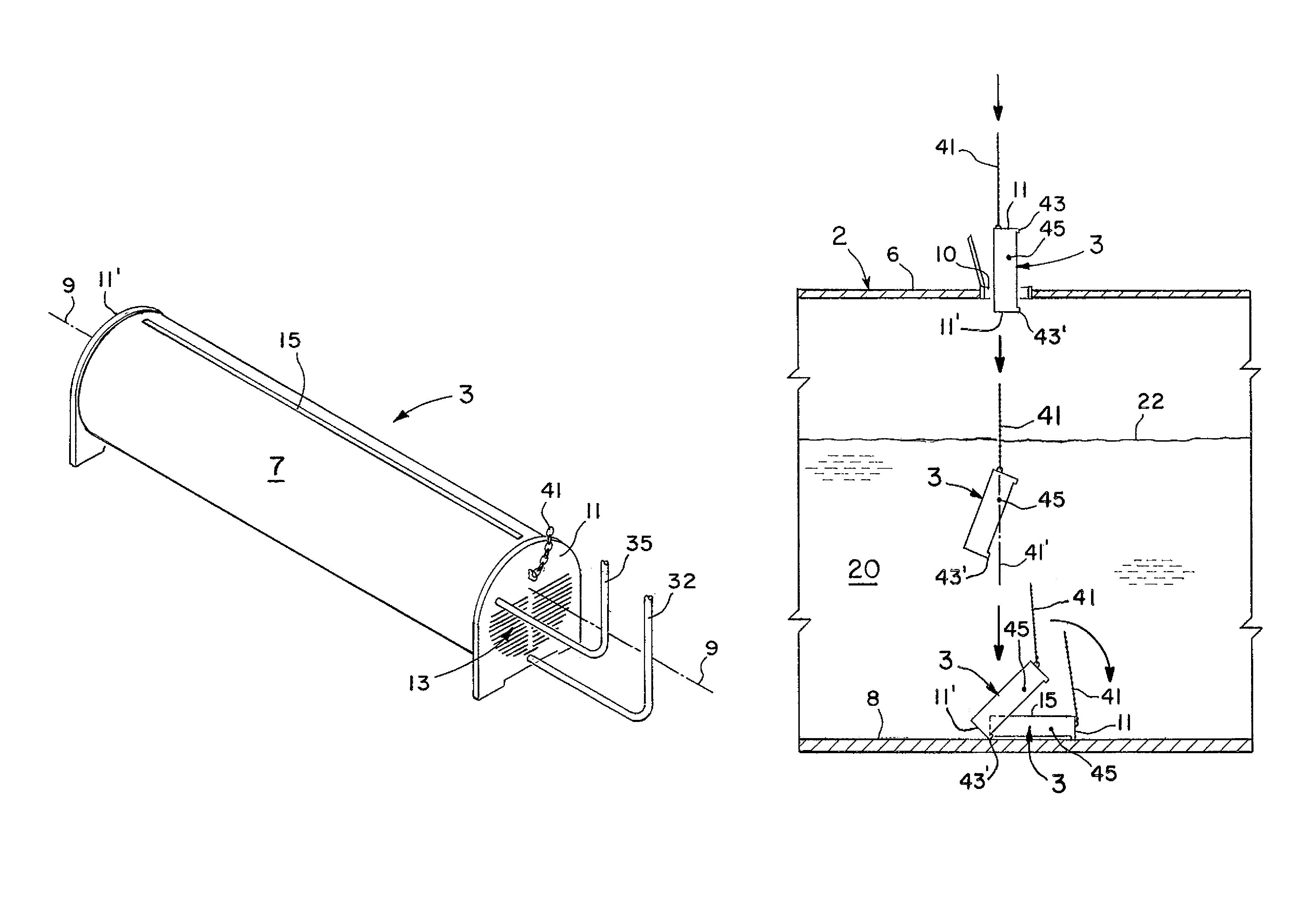
  • Application Information

AI Technical Summary

Benefits of technology

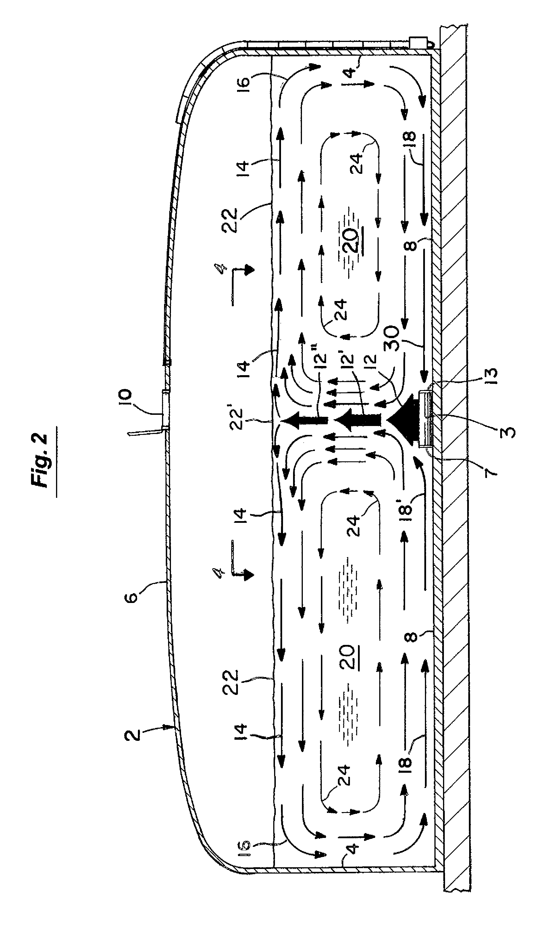
[0009]The substantially planar discharge presents a very large surface area for its volume to the adjacent water and induces a very large volume of tank water to flow with it. The discharge from the submerged driving unit is substantially laminar and travels upwardly to the surface of the water and substantially radially outwardly to the sides of the tank. It then flows downwardly to the tank floor and substantially radially inwardly along the tank floor to the submerged driving unit. In doing so, this primary circulation pattern in turn induces secondary flow patterns within the body of water to thereby thoroughly mix the water in the entire tank and to do so in a substantially laminar manner.
[0010]The driving unit of the circulation system is additionally designed to be received through the relatively small access opening of the tank in a completely assembled conditioned. It can thereafter be lowered to the tank floor by a flexible line to automatically assume the desired operating orientation without the need for any workers to enter the tank. The driving unit can also be raised out of the tank through the access opening without the necessity of any workers having to enter the tank.

Problems solved by technology

A physical problem with many such tanks is that they normally have only a relatively small access opening (e.g., 18-24 inches wide) which is designed primarily just to permit an individual worker to pass through to inspect or repair the tank.
This often requires special, elaborate, and costly training and following strict regulatory and other safety procedures.
Any unexpected or prolonged delays in bringing the tank back on line can thereafter be quite costly and in some cases present safety concerns to the community.
The same problems are presented if the circulation system placed in the tank subsequently breaks down and workers must enter the tank to repair it.

Method used


Image

  • Submersible water circulation system for enclosed tanks
  • Submersible water circulation system for enclosed tanks
  • Submersible water circulation system for enclosed tanks

Examples


Embodiment Construction

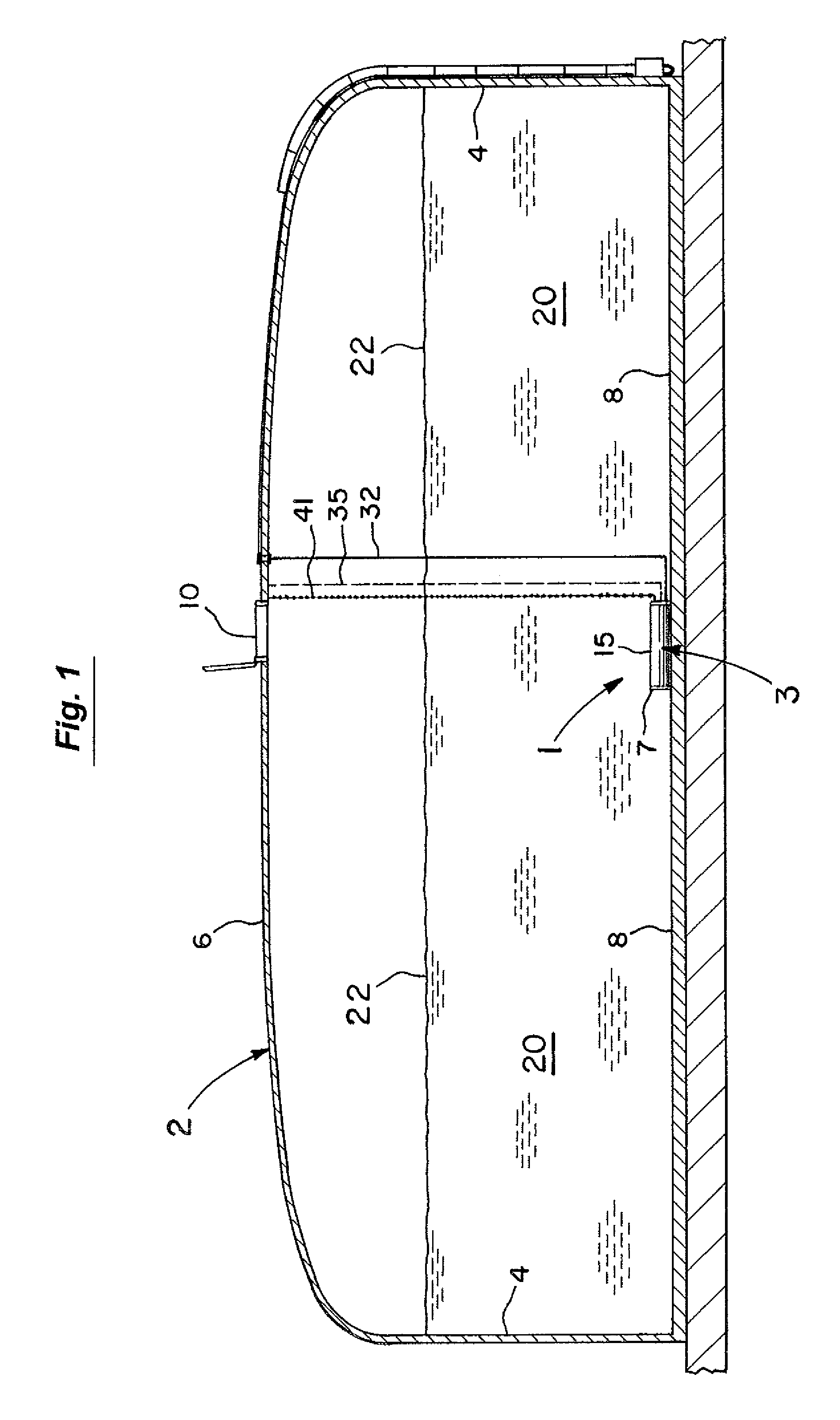
[0024]As shown in FIGS. 1-3, the circulation system 1 of the present invention is primarily intended for use to circulate water (FIGS. 2-3) in an enclosed water tank 2. Such tanks 2 are commonly used to contain water for municipalities, fire prevention, and industrial purposes. The tanks 2 (FIG. 1) typically have side and top walls 4,6 and a floor 8. The tank size can vary but typically holds about 300,000-500,000 gallons with some larger ones more on the order of 2 to 3 million gallons and are about 50-75 feet wide and 30 or more feet high. The tanks 2 also usually have a fairly small access opening at 10 (e.g., 18-24 inches wide) in the top wall 6 that is primarily designed to permit a single worker to pass through to inspect or repair the interior of the tank 2. In some cases, the access opening 10 may have safety bars or other restrictions and its width may be only 12 inches or less and not even permit any entry by a worker. The present circulation system 1 of FIGS. 1-3 in this ...


PUM

PropertyMeasurementUnit
sizeaaaaaaaaaa
widthaaaaaaaaaa
weightaaaaaaaaaa

Abstract

A submersible, water circulation system for enclosed tanks such as used by municipalities, fire districts, and industries. The system includes a driving unit having a shell extending along an axis with a pump supported within the shell. The shell has at least one inlet and at least one outlet and is positionable on the floor of the tank with the outlet facing upwardly. In operation, the pump continuously draws an incoming flow of water from outside of the driving unit adjacent the tank floor through the inlet of the driving unit and preferably drives all of the continuously incoming flow out through the upwardly facing outlet. The upwardly facing outlet is preferably a thin, elongated slot that creates a thin, substantially planar discharge of water therethrough that presents a very large surface area for its volume and induces water adjacent the shell to move upwardly with it.

Description

BACKGROUND OF THE INVENTION[0001]1. Field of the Invention[0002]This invention relates to the field of circulation systems for water tanks and more particularly to the field of circulation systems for enclosed tanks such as used for municipalities, fire protection, and industrial purposes.[0003]2. Discussion of the Background[0004]Municipalities, fire districts, and industries commonly use enclosed water tanks. Such tanks typically hold about 300,000-500,000 gallons with some larger ones more on the order of 2 to 3 million gallons and are about 50-75 feet wide and 30 or more feet high. The water in these tanks is preferably kept mixed by an internal circulation system to maintain its freshness, particularly in municipal water tanks, and to avoid water quality problems such as bacteria growth and nitrite development.[0005]A physical problem with many such tanks is that they normally have only a relatively small access opening (e.g., 18-24 inches wide) which is designed primarily just...

Claims


Application Information

Patent Timeline
Patent Type & Authority Patents(United States)
IPC IPC(8): F04B17/00B63H11/103F04B23/00E03B11/00B05B1/14F04B41/00F04B35/00B05B1/20
CPCE03B11/00Y10T137/86035Y10T137/85954B01F27/25F04B23/021F04D13/08F04D29/4293F04D29/406F04D29/007F04D13/086F04D13/16
Inventor WALTER, DOUGLAS P.BLETH, JOEL J.TORMASCHY, WILLARD R.SIMNIONIW, COREY M.ZENT, JONATHAN L.
Owner IXOM OPERATIONS
Learn More