Thermal solar energy collector

a solar energy collector and solar energy technology, applied in the field of thermal solar energy, can solve the problems of air quickly oxidizing the external surface of air, reducing the effective collection of heat, and transferring to the heat-conducting fluid, and achieve the effect of easy assimilation of expansion

Inactive Publication Date: 2014-12-23
UNIV MADRID POLITECNICA
View PDF24 Cites 6 Cited by
  • Summary
  • Abstract
  • Description
  • Claims
  • Application Information

AI Technical Summary

Benefits of technology

[0010]The invention consists in placing the radiation absorbent surface, and its matrix or supporting body, inside of which the heat-conducting fluid flows, in the interior of a big airtight box or receptacle that has a wall constituted by a transparent cover which is penetrated by the radiation to be absorbed; and the rest of the walls will be made of materials which will include mechanically strong structures, as well as thermal insulation; proposing an arrangement of the essential thermal component in such a way that it easily allows the assimilation of its expansions without altering the airtightness of the receptacle or box, which will be, in a first option of the invention, in vacuum conditions.
[0011]The component arrangement helps to minimize heat losses by conduction and convection towards the exterior; and the chemical aggression to the external layer of the radiation absorbent surface is minimized as well, thanks to the internal vacuum and the absence of oxygen. As an alternative to vacuum, the invention provides for the injection of an inert gas, such as nitrogen, in the interior of the receptacle, with an active system for maintaining the pressure vis-à-vis any change of temperature in the filling gas; being it also possible to place a double thin transparent cover, but with very low mechanical stress and low heat losses by convection. In any case, the expansions of the essential thermal component elements will be completely compensated, without creating stresses which may rapidly damage any element. Additionally, in the case of the more elaborate option of the invention, the external (local atmospheric pressure) and the internal pressure of the box or receptacle, will be equaled, so that the glass cover will be subjected to equal pressures on both faces, thus without suffering any mechanical stress difficult or impossible to withstand by glass or any other similar transparent material, in which it would be difficult to guarantee the resistance with a pressure difference of one atmosphere (1 bar, or 100,000 Pa) if the surface dimensions of the cover are large.
[0023]According to another particular embodiment, the means for delivering heat-conducting fluid to the collecting tube bundle have a distributor head to which the heat-conducting fluid arrives through an inflow conduit that goes through the rear wall of the airtight box through a hole in the rear wall, in which there is a fourth spherical seal. Besides, the means for collecting heat-conducting fluid from the bundle have a collecting funnel connected by its larger end to the outlet end of the collecting tubes and by its smaller end to an outlet conduit that goes through the rear wall of the box through a hole in the rear wall, in which a third spherical seal is provided. Additionally, this embodiment may present a high conductivity metallic screen which is fixed to the front part of the tube bundle, which is covered with a layer having high absorptivity and low emissivity to radiation, also painted or adhered.

Problems solved by technology

In these two patents, two especially serious problems of this panel or collector arrangement or configuration are evident: as these tubes are bare, the natural convection of the circulating air extracts a lot of heat from the irradiated surface, thus decreasing the effectively collected heat, that is, transferred to the heat-conducting fluid, with which the performance of the collector is low or very low; and besides, the oxygen of the air may quickly oxidize the external surface of the hot tube, which will have to be painted with a substance having a high solar absorptivity and a low emissivity, properties which are degraded when the oxygen chemically reacts with said especial paint layer.
This solution, however, has a problem, namely, that the glass of the transparent cover has to work with pressure differences between its walls of approximately one atmosphere, that is, about 100,000 pascals.
This pressure difference is very high for a material having a very low elastic limit, such as glass (and it would be even worse for some transparent plastics, because they would also have to withstand temperatures much higher than room temperature, though not as high as the ones of the radiation absorbent surface).
This means that the dimensions of the glass cover (or the cover in general), will be very limited by the internal mechanical stresses induced by the aforementioned pressure difference.
The glass cover could be very thick, to increase the transverse moment of inertia, thus decreasing the internal stress needed for balancing the induced bending moment, but this possibility presents, in turn, another inconvenience, since there is not any absolutely transparent glass, and the thicker the glass is, the greater the amount of absorbed radiation within itself there would be, which generates higher internal temperatures, and a greater gradient for it, because it is only refrigerated through the external wall, which generates the appearance of mechanical stress induced by thermal differences, that may also be larger than the ones produced by the external and internal pressure difference.
Along with the problems highlighted, another equally important problem should be noted, namely, that the expansions produced when the collector elements go from room temperature to the operation one, which may imply an increase of 500° C. or equal Kelvin in the SI system.

Method used


Image

  • Thermal solar energy collector
  • Thermal solar energy collector
  • Thermal solar energy collector

Examples


Embodiment Construction

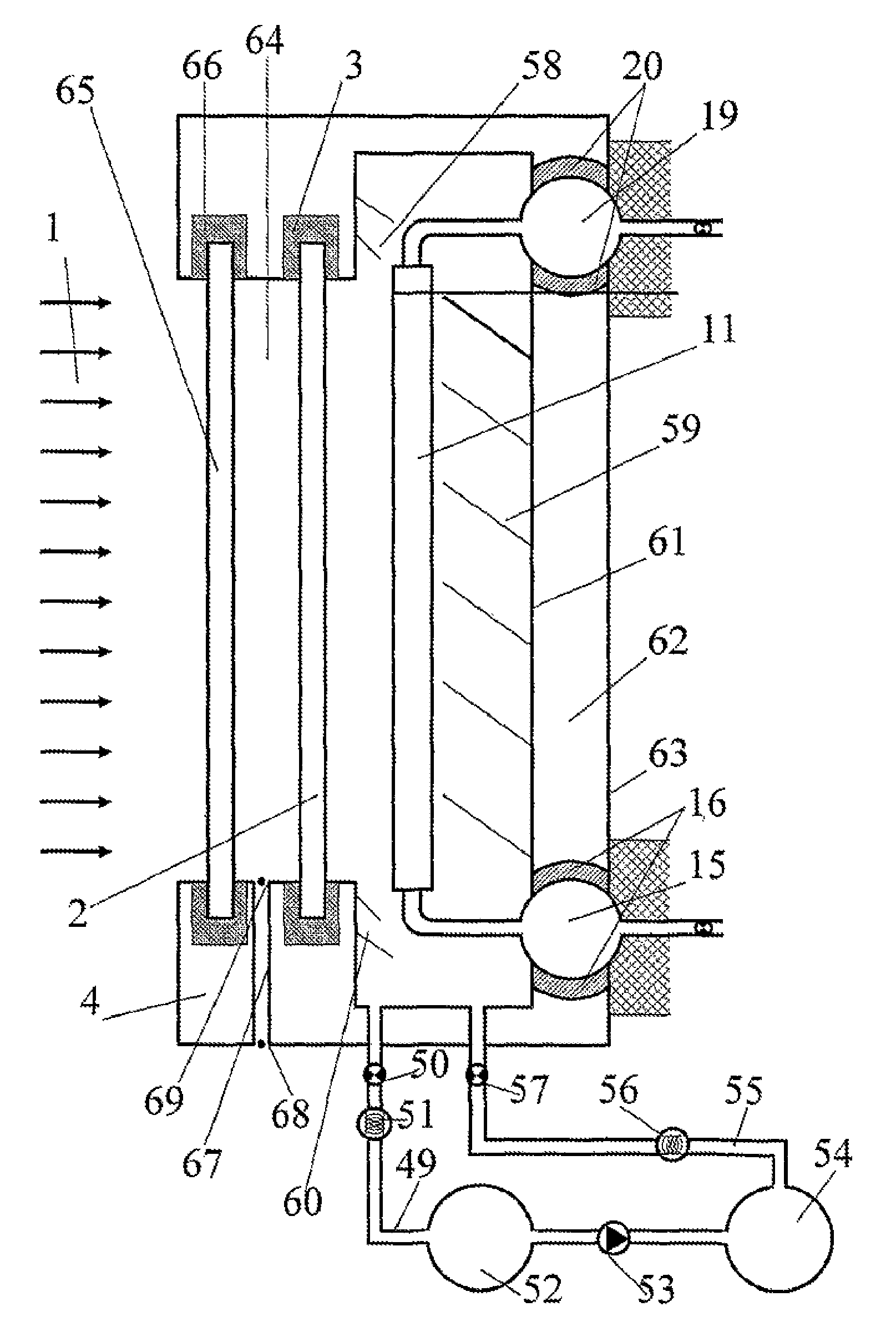
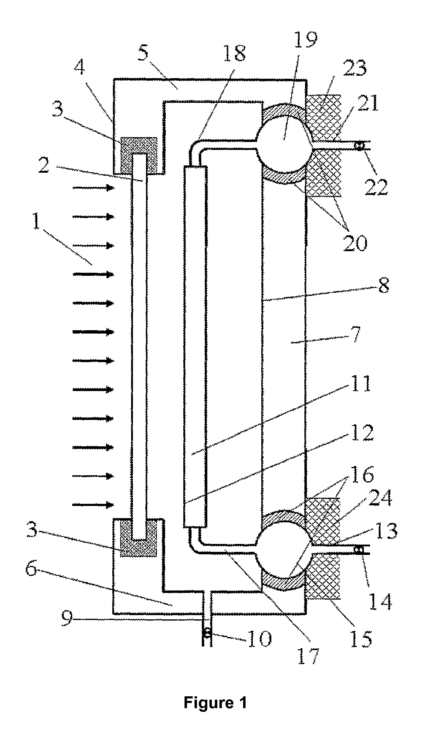
[0159]FIG. 1 represents a cross-sectional view of the general configuration of the proposed invention, showing the radiation striking the collector, 1, which may be direct from the sun, though in general it will come from several mirrors which concentrate it on the collector, to achieve higher temperatures, as the received intensity is larger, in power per surface unit, that is, watts per square meter. The radiation will mainly cross the transparent cover 2, which is embedded, through a seal 3 in the front wall 4 of the box 100 of the collector. This box 100 is airtight, as it is closed by the aforementioned front part, comprising that said wall plus the cover 2, as well as the upper walls, 5, and lower walls, 6, plus the side walls, without any especial function to mention, plus the rear wall, 7, which is not continuous rather it has bores where the heat-conducting fluid inlet tanks, 15, and outlet tanks, 19 rest; though the assembly is airtight due to the seals of the inlet tank, ...


PUM


Abstract

Thermal solar energy collector, in which a solar radiation absorption panel, inside which the heat-conducting fluid flows, is situated inside a parallelepipedal box, with an opening having a transparent cover at the front, which may be doubled so as to leave an atmospheric space in the middle. The rear wall of the box has a system of seals and reservoirs which are inset in the wall so that they accommodate the expansion and contraction of vertical tubes of the panel and horizontal connections by means of gentle changes in curvature of the tube bends and slight rotations of the reservoirs, with the addition of a system for filling the box with an inert gas, the pressure of which may be chosen from a range of between a thousandth of an atmosphere and one atmosphere, there being provided for this purpose an external gas circuit, with low- and high-pressure tanks, an intermediate compressor.

Description

[0001]This application is a National Stage Application of PCT / ES2009 / 000557, filed 3 Dec. 2009, which claims benefit of Ser. No. P200803767, filed 31 Dec. 2008 in Spain and which applications are incorporated herein by reference. To the extent appropriate, a claim of priority is made to each of the above disclosed applications.TECHNICAL FIELD OF THE INVENTION[0002]The invention refers to the field of thermal solar energy, particularly to the one that uses the concentration of source radiation, reflected by some steerable mirrors, and striking on some collectors that absorb part of said radiation to reach high temperature in the beneficial good, which generally materializes in a heat-conducting fluid that carries the solar heat absorbed to a thermodynamic cycle. Within this field the invention refers to collectors themselves, where there is a flat or curve surface which absorbs radiation, and which constitutes the external surface of a body inside which the aforementioned heat-conduc...

Claims


Application Information

Patent Timeline
Patent Type & Authority Patents(United States)
IPC IPC(8): F24J2/46F24J2/26F24J2/24F24J2/50F24S10/40F24S10/70F24S10/75F24S20/20
CPCF24J2002/502F24J2/465Y02E10/44F24J2/4636F24J2/265F24J2/51F24J2/4647F24J2/463F24J2/4645F24J2/345F24J2/07F24J2/507F24J2/4616F24S10/753F24S20/20F24S40/46F24S40/58F24S40/80F24S60/30F24S80/30F24S80/453F24S80/54F24S80/60F24S80/70F24S2080/502Y02E10/40
Inventor MARTINEZ-VAL, PENALOSA, JOSE, MARIA
Owner UNIV MADRID POLITECNICA
Why Eureka
Try Eureka