Current collector and energy transmission system

a current collector and energy transmission technology, applied in the direction of power current collectors, electric vehicles, electric power, etc., can solve the problems of cranes, lines being wound and unwound, cranes cannot be displaced, etc., to achieve the effect of simple connection of current collectors and non-damaging displacement of current collectors

Inactive Publication Date: 2014-12-23
CONDUCTIX WAMPFLER
View PDF18 Cites 2 Cited by
  • Summary
  • Abstract
  • Description
  • Claims
  • Application Information

AI Technical Summary

Benefits of technology

[0008]The present invention therefore is based on the objective of eliminating the above-described disadvantages and making available a current collector, as well as an energy transmission system, that allows an energy-saving, reliably contacting and non-damaging displacement of the current collector along a conductor line, as well as a simple connection of the current collector to the conductor line. Only low lateral forces should occur between the current collector and the conductor line, in particular, during the displacement of the current collector on the conductor line.

Problems solved by technology

This known technique has the disadvantage that the line being wound and unwound needs to be placed on the ground without introducing significant tensile forces into the line.
In addition, the line may become tangled while it is being wound or unwound such that the crane can no longer be displaced.
The electrical connection of the RTG cranes needs to be disconnected at the empty loading berth and reconnected at the full loading berth in a complicated, hazardous, and time-consuming fashion.
In addition, the displacement of the RTG cranes by means of internal combustion engines is harmful to the environment and is becoming more and more expensive due to rising fuel prices, such that electric drives should be provided for movement within longitudinal lanes while the internal combustion engines should be used only for the free travel between the longitudinal lanes.
However, since cranes of this type consist of very large systems that are typically used outdoors and therefore subjected to unfavorable ambient conditions, movements of the crane need to be decoupled as well as possible from movements of a current collector trolley that is connected to the crane and can be displaced on the conductor line.
Such a solution is very disadvantageous for conductor line current collector trolleys that are guided along a conductor line on a guide.
In this case, a force needs to be continuously exerted transverse to the traveling direction, i.e., transverse to the longitudinal direction of the conductor line, such that the energy consumption increases.
In addition, the constant pressing forces exerted transverse to the traveling direction leads to increased friction between the current collector trolley and the conductor line such that the energy consumption is additionally increased.
Consequently, the displacement of the current collector trolley along the conductor line requires a significantly higher expenditure of force and energy.
Since the current collector trolley is continuously pressed against the conductor line transverse to the traveling direction, the sensitive contacting between the sliding contacts and the longitudinal branches of the conductor line may become damaged.
If the displaceable devices should be additionally displaced between several conductor lines at different locations as it is the case, e.g., with RTG cranes, damage may occur due to the protruding pantograph.

Method used


Image

  • Current collector and energy transmission system
  • Current collector and energy transmission system
  • Current collector and energy transmission system

Examples


Embodiment Construction

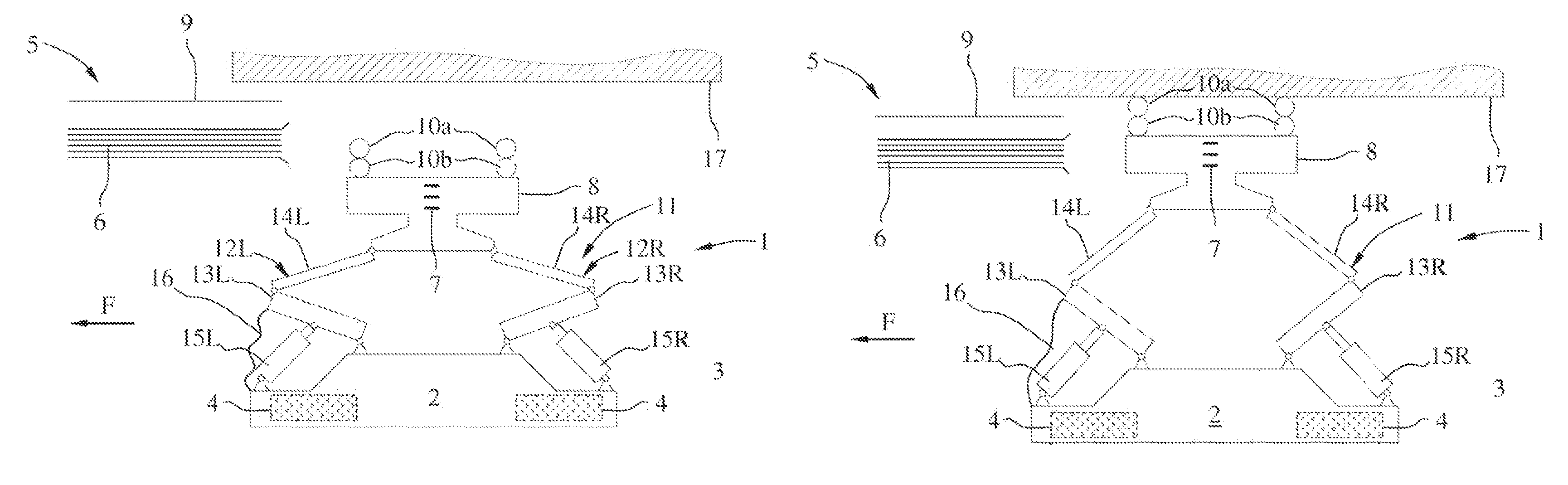
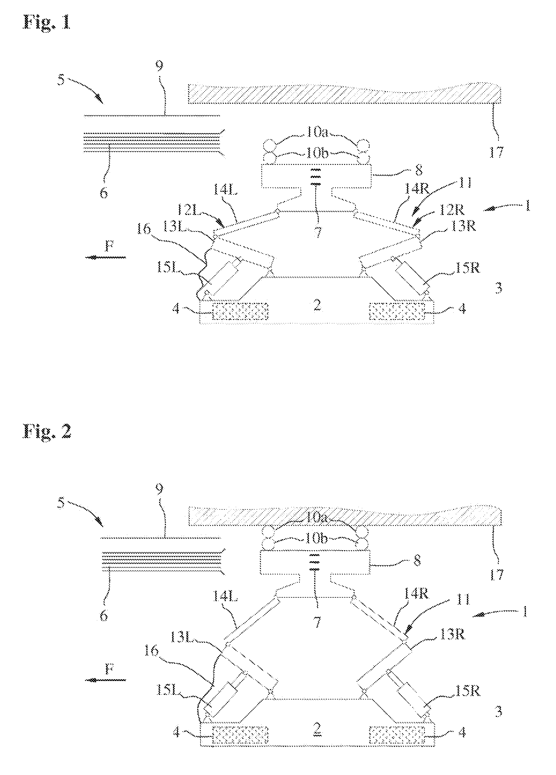
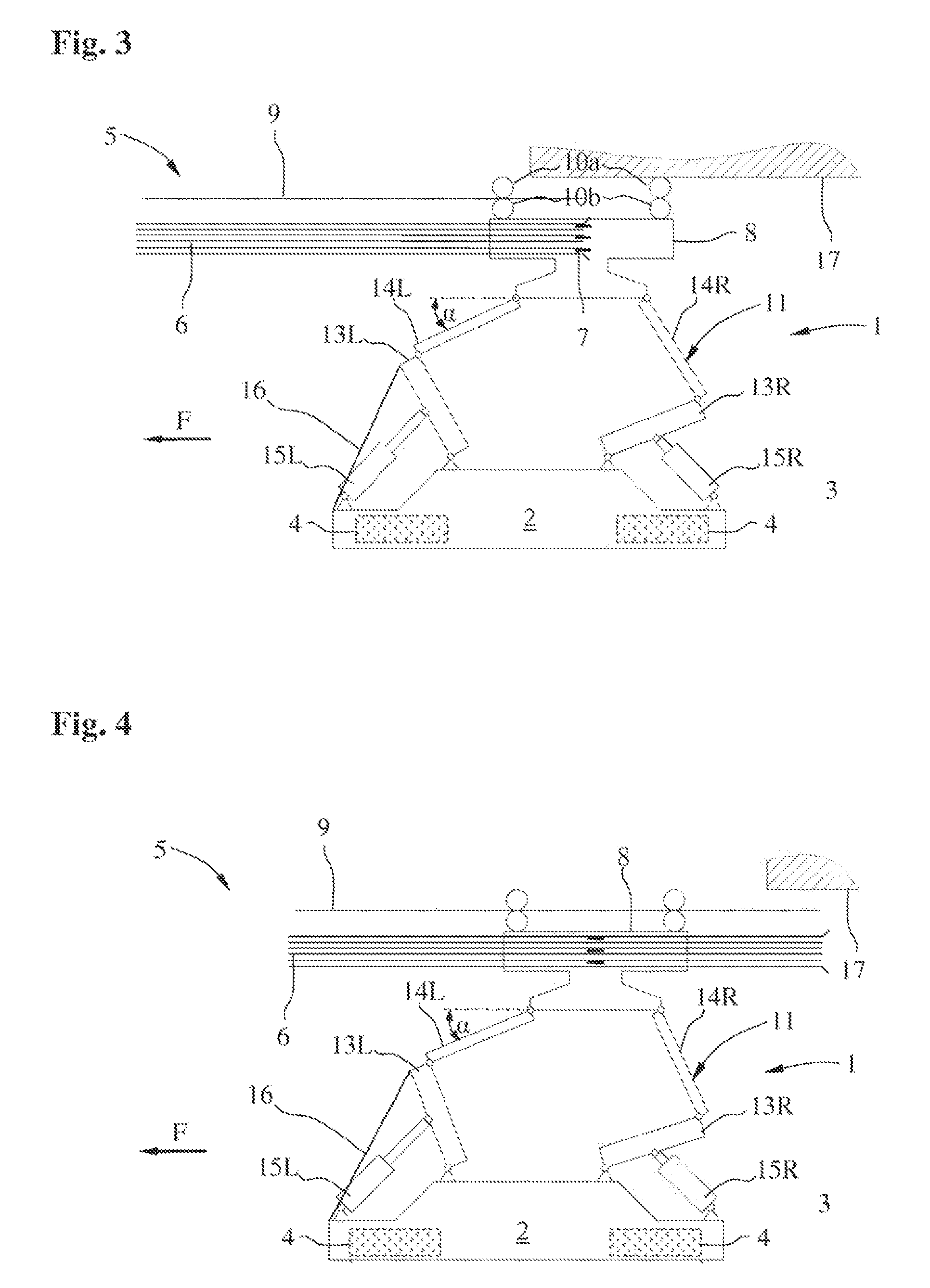
[0035]FIG. 1 shows a schematic top view of a first embodiment of an inventive energy transmission system with an inventive current collector 1 in an idle position.

[0036]The current collector 1 is mounted on a traveling pedestal of a crane 2 that can be displaced on the ground 3 in—and opposite to—a traveling direction F by means of an electric travel drive. In the drawings, the crane 2 is displaced on the ground 3 on graphically indicated rubber tires 4. The crane 2 may consist of a container-loading crane or an RTG crane.

[0037]A generally known conductor line 5 is provided in order to supply the crane 2 with electric energy via the current collector 1. The conductor line 5 features a plurality of voltage-carrying or current-carrying line branches 6 that are merely indicated in FIGS. 1-4. In FIGS. 3 and 4, sliding contacts 7 of a current collector trolley 8 of the current collector 1 engage into the line branches 6 from above in order to supply the crane with electric energy. One ex...


PUM


Abstract

The invention relates to a current collector 1 for a device 2 that can be displaced with and against the driving direction F along a conductor line 5, comprising a current collector cart 8 for the guided displacement along a guide element 9 of the conductor line 5, and an energy transmission system. The invention solves the problem of providing a current collector and an energy transmission system, which enable an energy-conserving, contact-reliable and damage-free displacement of the current collector along a conductor line and a simple connection of the current collector to the conductor line, in that at least one first lever assembly 12L between the current collector cart 8 and displaceable device 2 is provided with a first drive lever arm 13L, the first end of which can be connected in a rotatable manner to the displaceable device 2 and the second end of which is connected in a rotatable manner to a second end of at least one first tension lever arm 14L, the first end thereof being connected in a rotatable manner to a current collector cart, wherein a first adjustment drive 15L is provided in order to be able to move the current collector cart 8 between a retracted position on the displaceable device 2 and an extended position away from the displaceable device 2, and wherein a first locking device 16; 18L; 15L is provided, in order to lock the first drive lever arm 13L when displacing the displaceable device 2 in the driving direction F in a predetermined extended position.

Description

FIELD OF THE INVENTION[0001]The invention pertains to a current collector and to an energy transmission system.BACKGROUND OF THE INVENTION[0002]Known energy transmission systems in the form of conductor line systems of the type known, for example, from DE 196 47 336 A1 feature devices that can be displaced on a conductor line, e.g., cable roller assemblies or transport suspension gears of an overhead conveyor. These devices frequently carry electrical loads such as driving motors for displacing the displaceable devices on the conductor line. In order to supply these electrical loads, current collectors with one or more sliding contacts are usually provided on one or more of the displaceable devices and can be inserted into corresponding voltage-carrying and current-carrying longitudinal line branches of the conductor line. In this case, the current collectors are rigidly connected to the displaceable devices and only the contacting of the sliding contacts with the line branches is r...

Claims


Application Information

Patent Timeline
Patent Type & Authority Patents(United States)
IPC IPC(8): B60L5/36B60L5/00B60L5/12
CPCB60L5/12B60L5/36B60L2200/26
Inventor SCHMIEDLE, ANDREASZUMBACH, MELCHIOR
Owner CONDUCTIX WAMPFLER
Why Eureka
Try Eureka