Integrated fluid end

a technology of integrated fluid end and plunger pump, which is applied in the direction of valve housing, piston pump, positive displacement liquid engine, etc., can solve the problems of difficult field maintenance of y-block fluid section, few, if any, commercial success, and individual bore fatigue in the plunger pump housing

Inactive Publication Date: 2014-12-23
ALTIS INVESTMENTS LLC
View PDF54 Cites 39 Cited by
  • Summary
  • Abstract
  • Description
  • Claims
  • Application Information

AI Technical Summary

Problems solved by technology

Each individual bore in a plunger pump housing is subject to fatigue due to alternating high and low pressures which occur with each stroke of the plunger cycle.
Although several variations of the Y-block design have been evaluated, few, if any, have become commercially successful for several reasons.
One reason is that mechanics find field maintenance on Y-block fluid sections difficult.
For example, replacement of plungers and / or plunger packing is significantly more complicated in Y-block designs than in the earlier designs represented by FIG. 1.
This operation, which would leave the plunger packing easily accessible from the proximal end of the plunger bore, is not possible in a Y-block design.
Thus, a Y-block configuration, while reducing stress in plunger pump housings relative to earlier designs, is associated with significant disadvantages, such as cracks as shown in FIG. 4A.
Conventional valve designs incorporating secure placement of guides for both top and lower valve guide stems have been associated with complex components and difficult maintenance.
This very “fast” taper is insufficient to retain the seat in a locked position and when the seat is subjected to very high valve loads.
Thus, the seat shoulder is exposed to very high downward or axial loads, which results in the very high stresses in the fillet, as further discussed herein.
This shoulder results in very high stresses at the fillet at the corner of the fluid end taper and bottom shoulder.

Method used


Image

  • Integrated fluid end
  • Integrated fluid end
  • Integrated fluid end

Examples


Embodiment Construction

[0031]The following description is merely exemplary in nature and is in no way intended to limit the present disclosure, application, or uses.

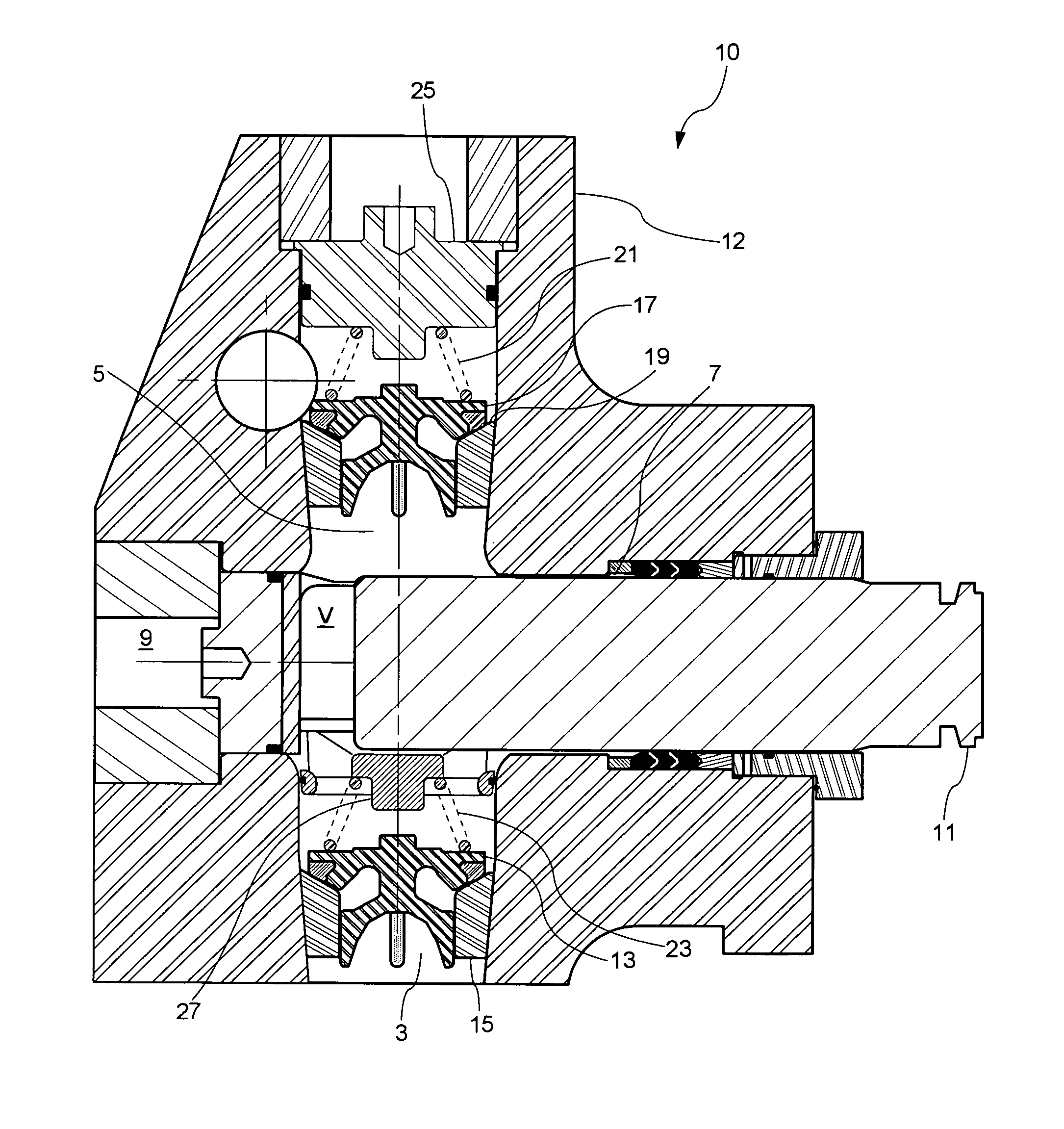
[0032]Referring again to the drawings, and particularly to FIG. 6 there is shown a cross-section of a right-angular plunger pump 10 made using a housing 12, and having suction bore 3, discharge bore 5, access bore 9 suction valve 13, seat 15, discharge valve 17, seat 19, plunger 11 present in a plunger bore 7, inner volume V, suction valve spring 23, suction valve spring retainer 27, discharge valve spring 21, discharge cover and spring retainer 25 according to some embodiments of the disclosure. According to embodiments of the disclosure exemplified by this FIG. 6, valve seats 15, 19 are present in suction bore 3 and discharge bore 5 respectively, so that the outer wall portions of valve seats 15, 19 are entirely present within a tapered portion of suction bore 3 and discharge bore 5. Stated another way, the portions of suction bore 3 and dis...


PUM


Abstract

Tapered valve guide and spring retainer assemblies are described for use in plunger pump housings that incorporate corresponding outwardly flared discharge and suction bores, as well as structural features for stress-relief. Plunger pumps so constructed are relatively resistant to fatigue failure because of stress reductions, and they may incorporate essentially any style of valves, including top and lower stem-guided valves and crow-foot-guided valves, in easily-maintained configurations. Besides forming a part of valve guide and spring retainer assemblies, side spacers may be shaped and dimensioned to improve volumetric efficiency of the pumps in which they are used. The present disclosure provides, for the first time, the use of tungsten carbide valve seats, which significantly increase durability and service life of a pump, especially when abrasive fluids are being pumped, as in various oilfield operations.

Description

CROSS REFERENCE TO RELATED APPLICATIONS[0001]This application is a continuation-in-part of, and claims the benefit of U.S. patent application Ser. No. 12 / 390,517 filed on Feb. 23, 2009 now U.S. Pat. No. 8,147,227, the entire contents of which is hereby incorporated herein by reference thereto.TECHNICAL FIELD[0002]The present disclosure generally concerns high-pressure plunger-type pumps useful, for example, in oil field operations. More particularly, the invention relates to fluid sections of such pumps and features provided thereto which impart heretofore unseen longevity and durability to such pumps when subjected to extreme service, including pumping of abrasive fluid materials.BACKGROUND OF THE INVENTION[0003]The statements in this background section merely provide background information related to the present disclosure and may not constitute prior art.[0004]Engineers typically design high-pressure plunger pumps useful in oilfield operations in two sections; a (proximal) power ...

Claims


Application Information

Patent Timeline
Patent Type & Authority Patents(United States)
IPC IPC(8): F04B7/00F16K27/00F04B53/10F04B39/00
CPCF04B53/007F04B53/16F04B53/1032F04B53/164F04B53/1017F04B53/102F04B53/1087Y10T137/7939
Inventor BLUME, GEORGE, H.
Owner ALTIS INVESTMENTS LLC
Why Eureka
Try Eureka