
Filter element wave gland seal

a filter element and wave gland technology, applied in the direction of moving filter element filters, filtration separation, separation processes, etc., can solve the problem that the canister cannot be properly screwed onto the head, and achieve the effect of convenient positioning and installation of the element in the socket, good seal retention, and rapid in-phase engagemen

Active Publication Date: 2014-12-23
PARKER INTANGIBLES LLC
View PDF16 Cites 52 Cited by
  • Summary
  • Abstract
  • Description
  • Claims
  • Application Information

AI Technical Summary

Benefits of technology

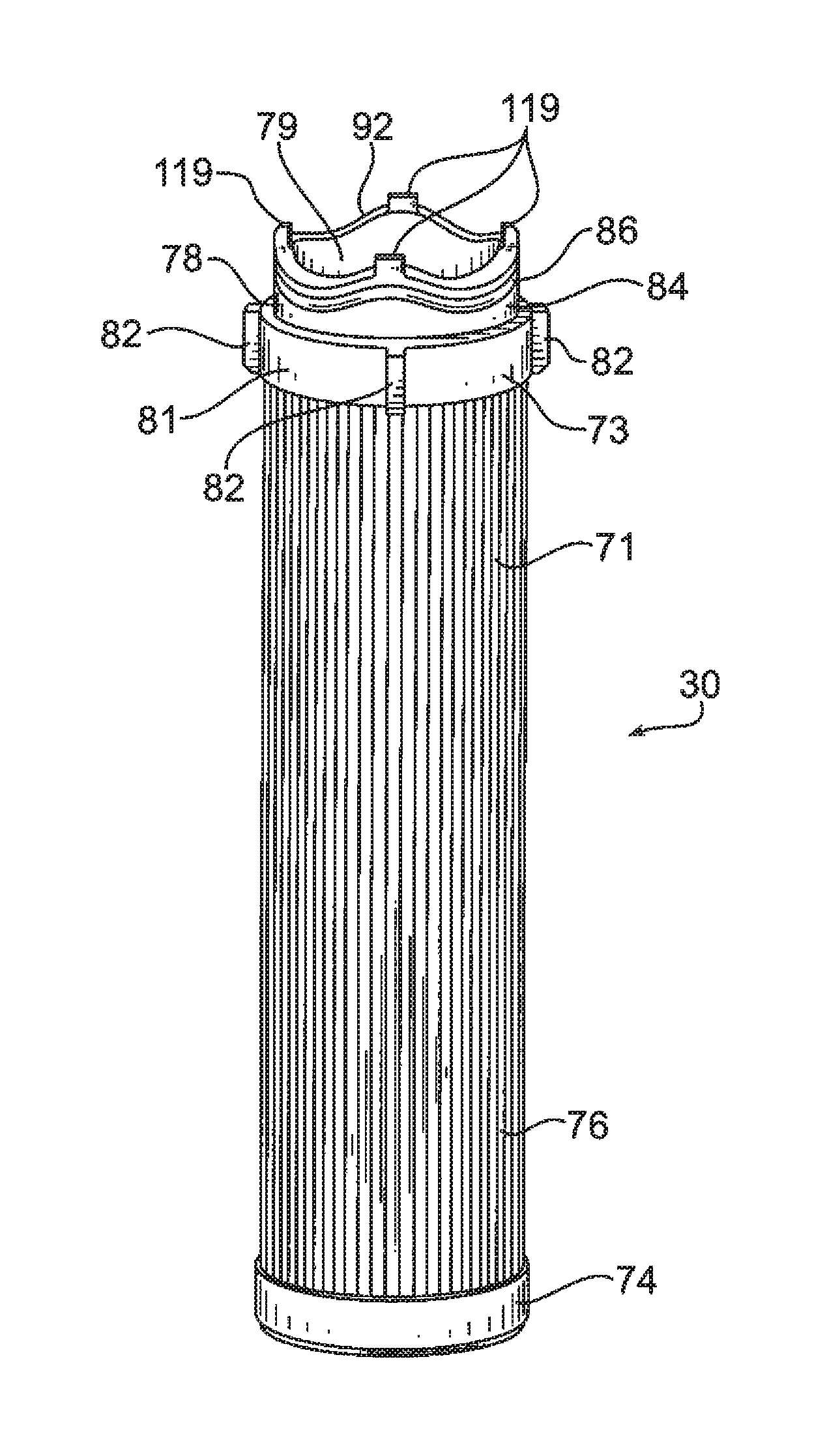
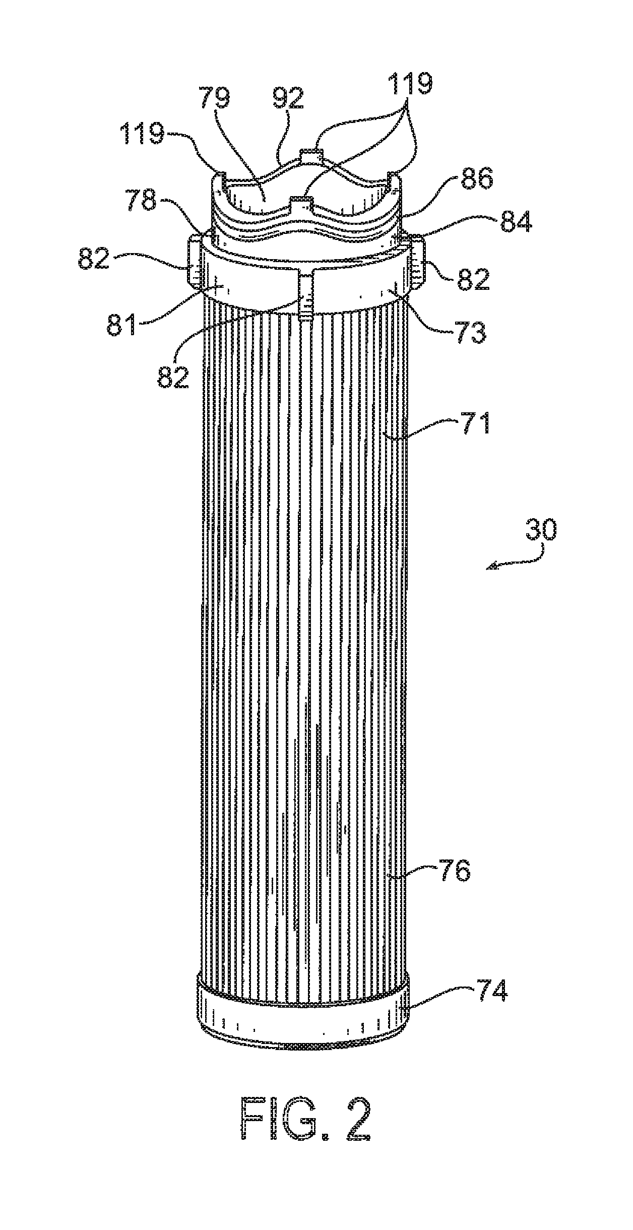
[0007]The annular body can have one or more tabs projecting axially outward from the distal end, which can be positioned at the points of maximum amplitude of the distal end. The tabs along the distal end of the end cap body are received in slots in the shoulder of the socket, which can be positioned at the points of minimum amplitude along the surface of the shoulder. Alternatively the tabs and slots could be reversed, with the tabs on the diaphragm and the slots in the end cap. Either way, the tabs and slots further facilitate positioning and installing the element in the socket.
[0008]Advantages of the present invention include good seal retention in the undulating groove of the end cap; rapid in-phase engagement between the end cap and socket during assembly; and a robust, positive seal between the end cap and the socket even during high differential pressures across plugged media.

Problems solved by technology

In other words, the canister cannot be properly screwed onto the head when the element is out of rotational alignment with the diaphragm, as the expanded element / diaphragm interface prevents the canister from being tightened-down.

Method used


Image

  • Filter element wave gland seal
  • Filter element wave gland seal
  • Filter element wave gland seal

Examples


Embodiment Construction

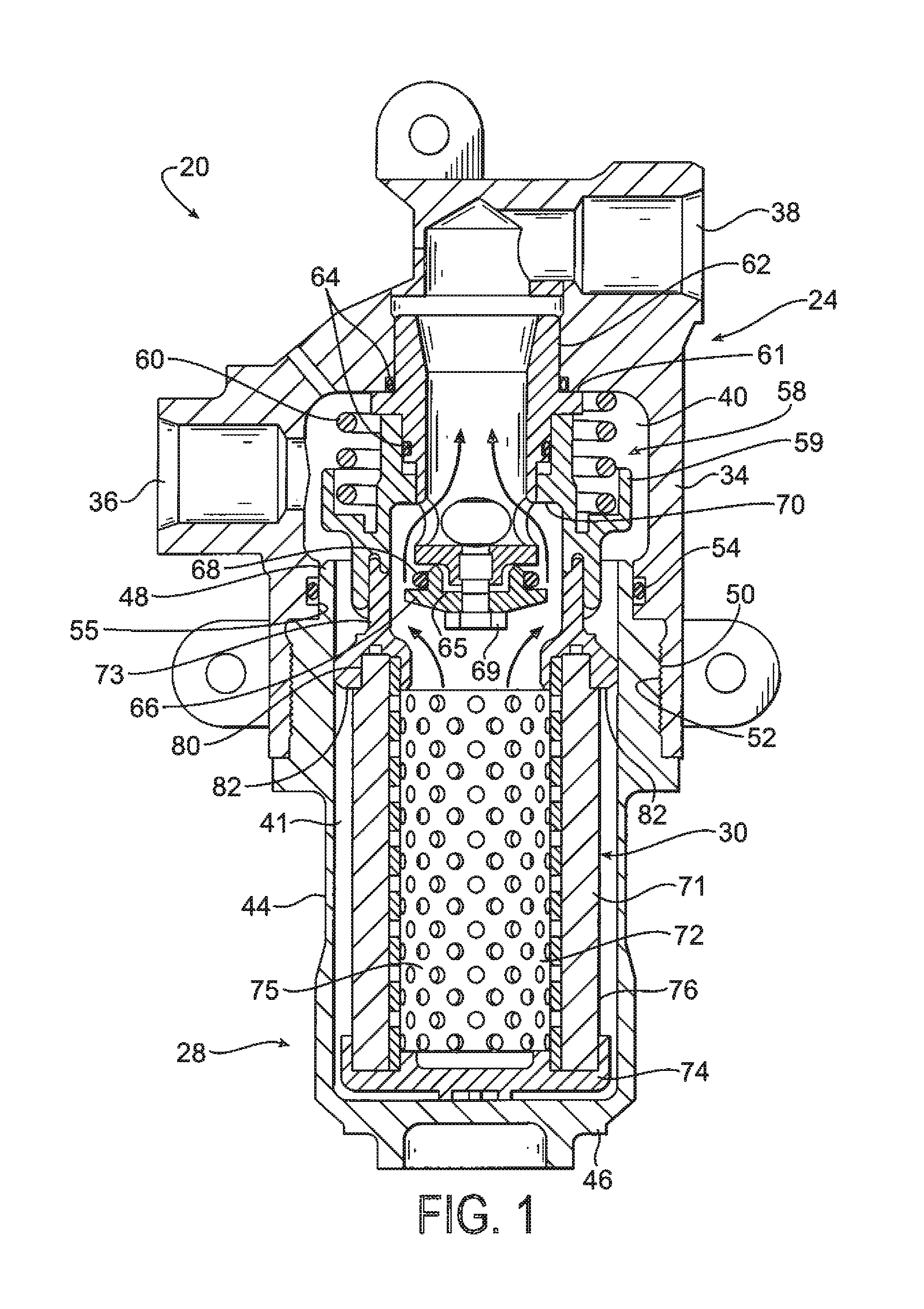
[0024]Referring to the Figures, and initially to FIG. 1, a filter module constructed according to the present invention is shown generally at 20. Filter module 20 can be used in a variety of applications, for example, hydraulic filter applications, where it is necessary or desirable to remove particulate and / or other contaminants from a hydraulic fluid stream. Module 20 generally includes a head assembly, indicated generally at 24, a cup-shaped bowl or canister, indicated generally at 28, and a filter element, indicated generally at 30, which is received and supported in bowl 28 and removes the contaminants and particulate in the fluid stream as it passes therethrough.

[0025]The head assembly 24 of the module includes a body 34 with an inlet port 36 which can be connected to receive fluid to be filtered from the system, and an outlet port 38 which can be connected to direct filtered fluid back to the system. Inlet port 36 directs incoming fluid into an inlet cavity 40 in the body whe...


PUM

PropertyMeasurementUnit
rotationaaaaaaaaaa
outer diameteraaaaaaaaaa
sinusoidal shapeaaaaaaaaaa

Abstract

A filter module includes a filter element with a ring of media and an end cap at one end of the ring. The end cap includes an annular body with a sealing member located around a surface of the body circumscribing a central opening, wherein the sealing member has a repeating, undulating, non-planar geometry. The axial, distal end of the annular body also has an repeating, undulating non-planar geometry, matching the geometry of the sealing member, and can have one or more tabs projecting axially outward from the distal end, positioned at a point of maximum amplitude of the distal end, and which are received in cooperating slots formed in a socket of a diaphragm, to facilitate positioning and installing the element into the module. The socket includes an outer wall having a matching non-planar geometry which receives and seals against the sealing member on the end cap.

Description

FIELD OF THE INVENTION[0001]The present invention relates generally to filter elements and filter modules, and to the interface between the element and a corresponding mating component.[0002]In some filtration applications, a replaceable filter element has an end cap which is connected to the head of a filter module. The module includes a canister which receives the element, and inlet and outlet ports in the head which direct fluid into and out of the module. The fluid passes through the filter element, which separates particles and other contaminants from the fluid which is then returned to the operating system. In order for the filter element to properly function and not leak, a positive seal must be maintained with the filter head. Typically, hydraulic filter elements use an O-ring supported along a plane in a straight cut or radial seal gland design. A sloped or angled seal gland design has been used, for example as shown in U.S. Pat. No. 7,494,017 for “Filter Element With Off-A...

Claims


Application Information

Patent Timeline
Patent Type & Authority Patents(United States)
IPC IPC(8): B01D35/153B01D29/21B01D29/96B01D29/15B01D35/30B01D29/13
CPCB01D2201/295B01D2201/4046B01D2201/34B01D2201/296B01D35/153
Inventor RAPIN, DANIEL, P.
Owner PARKER INTANGIBLES LLC
Learn More