
Battery charging system

a battery charging and battery technology, applied in the direction of electrochemical generators, process and machine control, instruments, etc., can solve the problems of non-safe provision of conventional electrical connections, large problem of single spiral winding magnetic flux distribution, and non-uniform magnetic flux distribution

Inactive Publication Date: 2014-12-23
CITY UNIVERSITY OF HONG KONG
View PDF40 Cites 178 Cited by
  • Summary
  • Abstract
  • Description
  • Claims
  • Application Information

AI Technical Summary

Benefits of technology

The present invention provides a battery charging system that can charge multiple electronic devices simultaneously. The charging surface is large enough to accommodate multiple devices and the primary charging circuit can charge them at the same time. The invention also allows for the device to move over the charging surface while being charged. The battery charging system employs a localized charging concept, which means energy is only transferred from the primary coil that is adjacent to the secondary coil in the device. This results in more efficient energy transfer and faster charging of the device.

Problems solved by technology

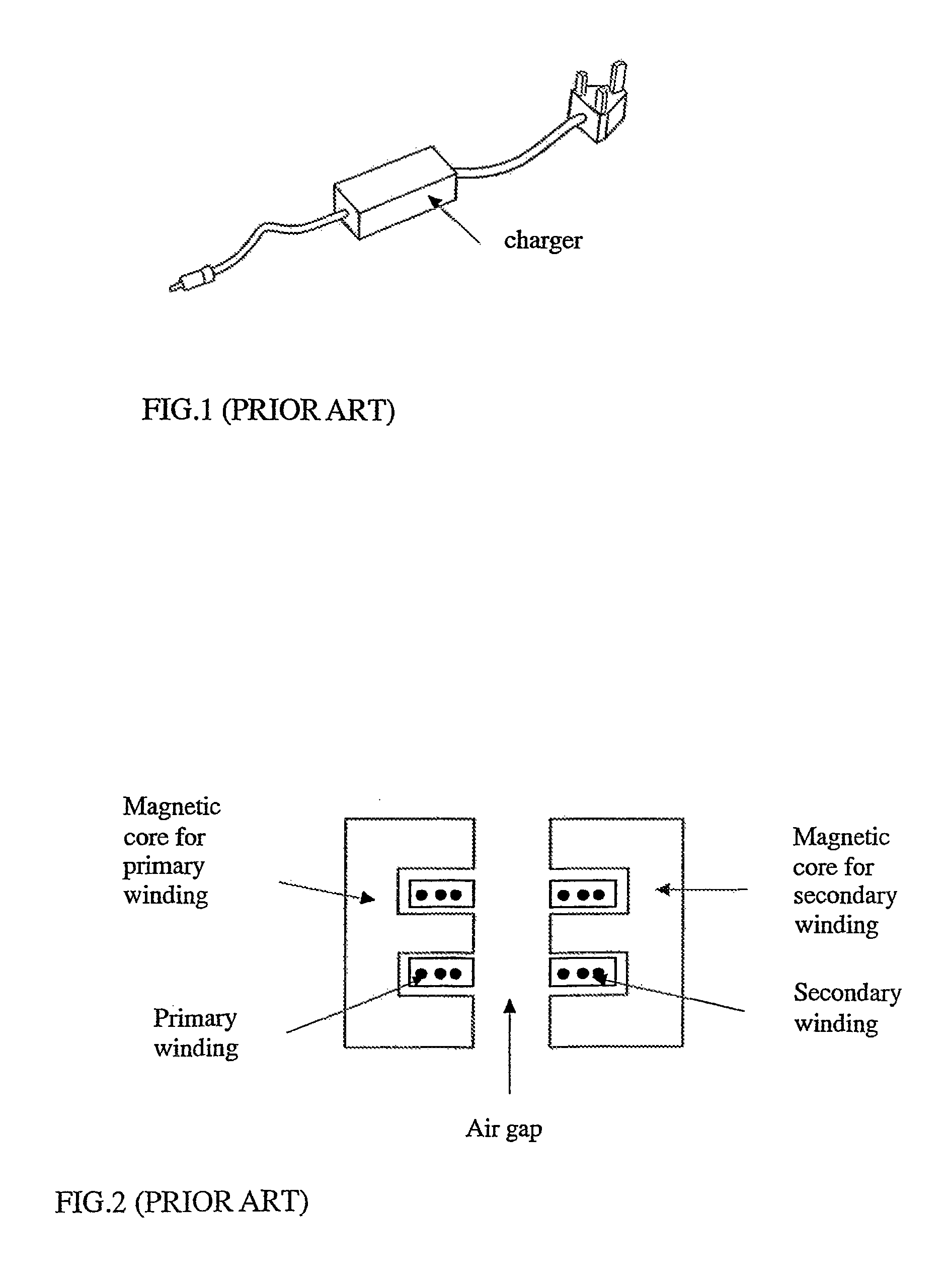
Inductive electronic chargers without direct physical electrical connection have been developed in some portable electronic equipment such as electric toothbrushes where because they are designed to be used in the bathroom in the vicinity of sinks and water, it is not safe to provide a conventional electrical connection.
However, the magnetic flux distribution of a single spiral winding has a major problem of non-uniform magnetic flux distribution.
This means that if the portable electronic device is not placed properly in the central region, the charging effect is not effective in this non-uniform field distribution.
Furthermore, without proper EMI shielding, undesirable induced currents may flow in other metallic parts of the portable electronic equipment.

Method used


Image

  • Battery charging system
  • Battery charging system
  • Battery charging system

Examples


Embodiment Construction

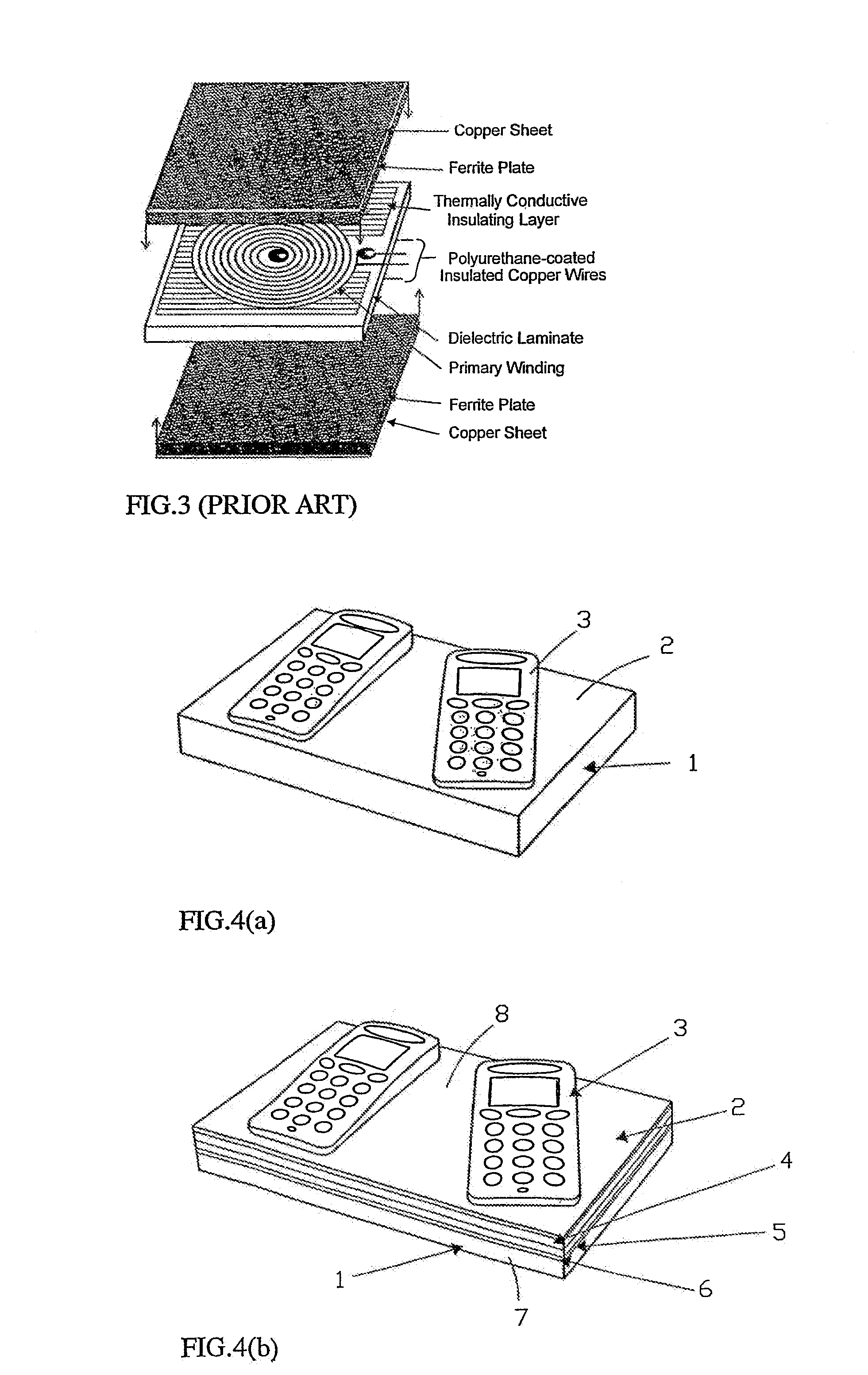
[0072]The present invention will now be described in respect of a preferred embodiment in the form of an inductive battery charger for portable electronic equipment such as mobile phones, handheld computers and personal digital assistants (PDA), and devices such as a wireless computer mouse.

[0073]Referring firstly to FIG. 4, the inductive charger system comprises two modules, a power delivering charger module that contains the primary circuit of a planar isolation transformer and a secondary circuit that is located in the portable electronic equipment to be charged. In this embodiment of the invention, the charger circuit is located within a housing 1 that is formed with a flat charging surface 2. The secondary circuit is formed in the portable equipment to be charged (in this example a mobile phone 3) and the equipment is formed with at least one planar surface. As will be seen from the following description the equipment is charged simply by placing the equipment on the surface so...


PUM

PropertyMeasurementUnit
frequencyaaaaaaaaaa
frequencyaaaaaaaaaa
frequencyaaaaaaaaaa

Abstract

There is provided a planar inductive battery charging system designed to enable electronic devices to be recharged. The system includes a planar charging module having a charging surface on which a device to be recharged is placed. Within the charging module and parallel to the charging surface is at least one and preferably an array of primary windings that couple energy inductively to a secondary winding formed in the device to be recharged. The invention also provides secondary modules that allow the system to be used with conventional electronic devices not formed with secondary windings.

Description

CROSS-REFERENCE TO RELATED APPLICATIONS[0001]This application is a continuation-in-part of U.S. patent application Ser. No. 12 / 950,814, filed Nov. 19, 2010, which is a continuation of co-pending U.S. patent application Ser. No. 12 / 486,572, filed Jun. 17, 2009, entitled “RECHARGEABLE BATTERY POWERED PORTABLE ELECTRONIC DEVICE,” which is a continuation of U.S. Pat. No. 7,576,514, granted Aug. 18, 2009, entitled “PLANAR INDUCTIVE BATTERY CHARGING SYSTEM” (as amended), which is a continuation of U.S. Pat. No. 7,164,255, granted Jan. 16, 2007, entitled “INDUCTIVE BATTERY CHARGER SYSTEM WITH PRIMARY TRANSFORMER WINDINGS FORMED IN A MULTI-LAYER STRUCTURE” (as amended), which is a continuation of PCT International Application PCT / AU03 / 00721, filed Jun. 10, 2003, and published under PCT Article 21(2) in English as WO 03 / 105308 on Dec. 18, 2003. PCT / AU03 / 00721 claimed benefit from British Applications 0213374.2, filed on Jun. 10, 2002; 0226893.6, filed on Nov. 18, 2002; and 0305428.5, filed o...

Claims


Application Information

Patent Timeline
Patent Type & Authority Patents(United States)
IPC IPC(8): H01M10/46H01F38/14H02J7/02H01F17/00
CPCH01F2017/008H01F38/14H02J7/025H02J7/0052H02J7/0042G05D1/0038H02J50/10H02J50/70H02J7/00
Inventor HUI, SHU, YUEN, RON
Owner CITY UNIVERSITY OF HONG KONG
Learn More