Fuel injection valve

a fuel injection valve and valve body technology, applied in the direction of fuel injection pumps, machines/engines, mechanical equipment, etc., can solve the problems of lowering the combustion efficiency, and achieve the effect of raising the flow rate accuracy

Active Publication Date: 2014-12-30
MITSUBISHI ELECTRIC CORP
View PDF13 Cites 7 Cited by
  • Summary
  • Abstract
  • Description
  • Claims
  • Application Information

AI Technical Summary

Benefits of technology

[0023]The present invention has been implemented in order to solve the problems in the foregoing conventional fuel injection valves; the objective thereof is to provide a fuel injection valve that can realize both the directivity of spray in the spray characteristics thereof and the atomization and that raises the flow rate accuracy in the flow rate characteristics.
[0027]In the fuel injection valve according to the present invention, in a flow path formed by the injection hole, there is provided a cylindrical portion, whose cross section is the radially minimum cross section of the injection hole, from the upstream side face of the injection hole plate to the plain of the concave; and assuming that D1 denotes the diameter of the injection hole and D2 denotes the diameter of the concave or the diameter of the concave in the circumferential direction of the virtual circle, the relationship 1.1<(D2 / D1)<3.0 is satisfied. As a result, atomization of the fuel is facilitated, and it is made possible that small-turbulence fuel, keeping a fast flow rate, is made to flow into the injection hole and while the fuel is pushed against the inner wall of the injection hole that is situated radially inside the valve seat, the fuel that has been efficiently atomized at each injection hole is injected; therefore, both the directivity and the atomization of the spray can concurrently be satisfied.
[0028]In the fuel injection valve according to the present invention, in a flow path formed by the injection hole, there is provided a cylindrical portion, whose cross section is the radially minimum cross section of the injection hole, from the upstream side face of the injection hole plate to the plain of the concave; and assuming that T1 denotes the thickness of the injection hole plate and T2 denotes the depth of the concave, the relationship 0.1<(T2 / T1)<0.8 is satisfied. As a result, the flow rate does not vary, and it is made possible that small-turbulence fuel, keeping a fast flow rate, is made to flow into the injection hole and while the fuel is pushed against the inner wall of the injection hole that is situated radially inside the valve seat, the fuel that has been efficiently atomized at each injection hole is injected; therefore, both the directivity and the atomization of the spray can concurrently be satisfied.

Problems solved by technology

However, when the fuel is sprayed, part of the spray, situated at a position that is away from the center axis of the spray, attaches to the inner wall of an intake port; therefore, some of the fuel travels on the inner wall of the intake port, becomes a liquid film, and flows into the combustion chamber in a delayed manner, thereby hindering the combustion efficiency from being raised.

Method used


Image

  • Fuel injection valve
  • Fuel injection valve
  • Fuel injection valve

Examples


embodiment 1

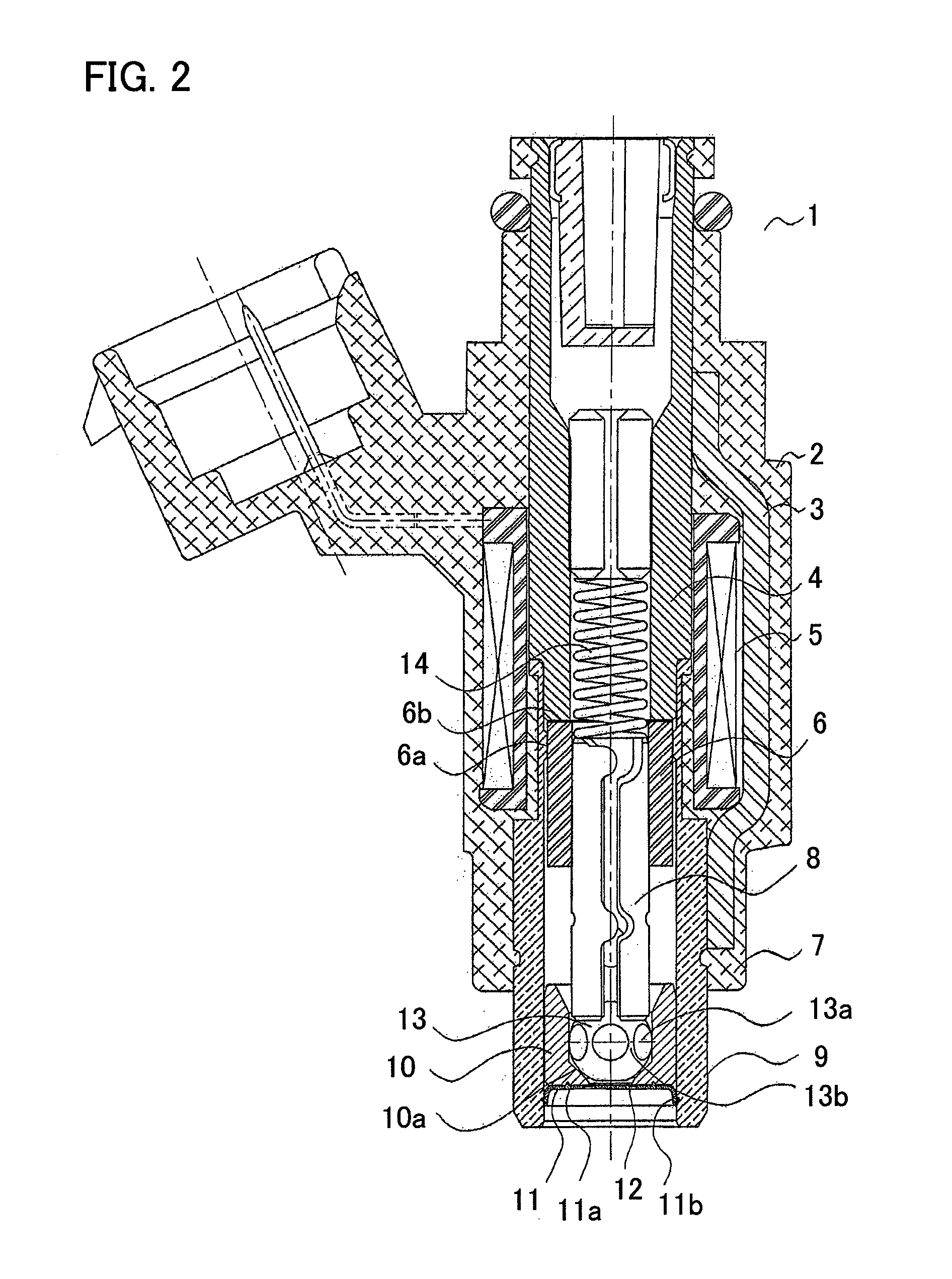
[0041]FIG. 2 is a cross-sectional view illustrating a fuel injection valve according to Embodiment 1 of the present invention. In FIG. 2, a fuel injection valve 1 is provided with a solenoid device 2, a housing 3 which is a yoke portion of a magnetic circuit, a core 4 which is a fixed iron core portion of the magnetic circuit, a coil 5, an armature 6 which is a moving core portion of the magnetic circuit, and a valve device 7. The valve device 7 is configured with a cylindrical valve body 8 having a ball-shaped front end portion 13 at the front end thereof, a valve main body 9, and a valve seat 10.

[0042]The valve main body 9 is pressed onto the end portion outer circumferential surface of the core 4 and then is welded and fixed on the core 4. The armature 6 is pressed onto the valve body 8 and then is welded and fixed on the valve body 8. At the downstream side of the valve seat 10, an injection hole plate 11 is welded and combined with the valve seat 10 at a welding portion 11a. Th...

embodiment 2

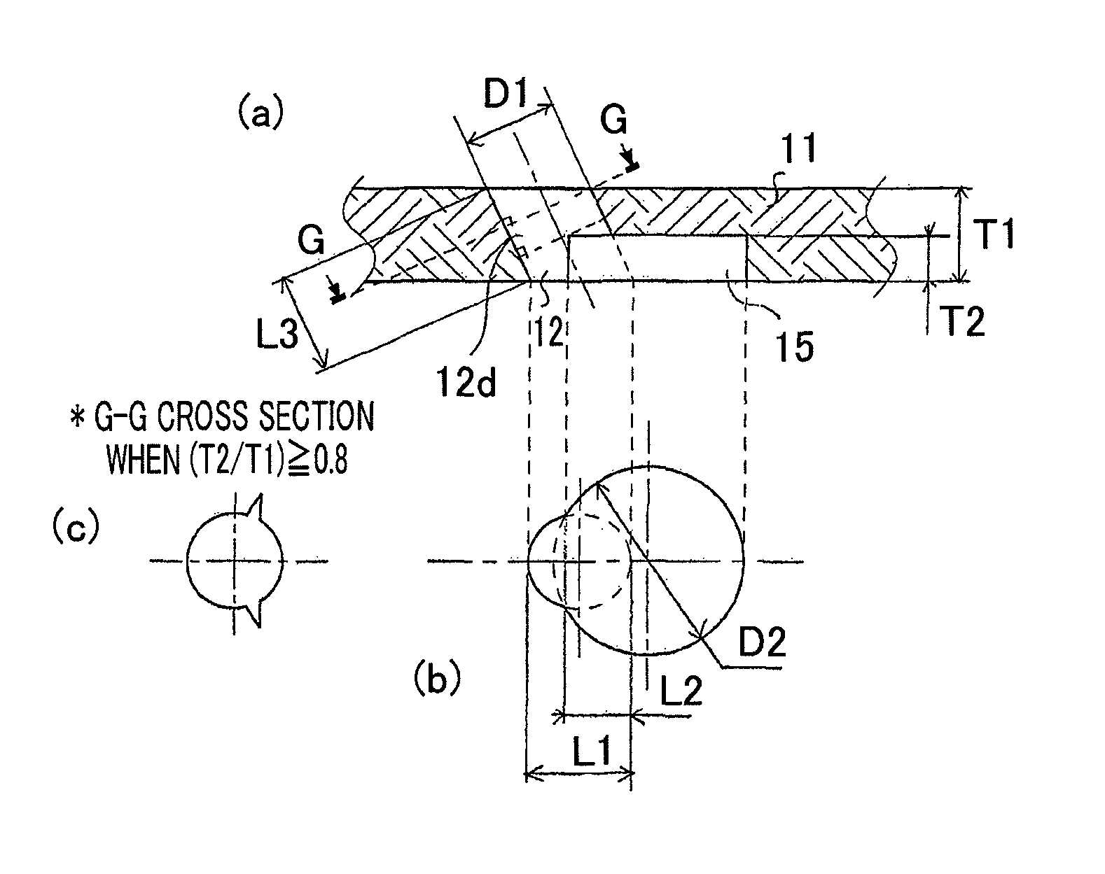
[0072]FIG. 10 is a set of explanatory views illustrating a fuel injection valve according to Embodiment 2 of the present invention; FIG. 10(a) is a cross-sectional view; FIG. 10(b) is a plan view taken along the arrow J in FIG. 10(a); FIG. 10(c) is an enlarged cross-sectional view taken along the K-K line; and FIG. 10(d) is an enlarged cross-sectional view taken along the L-L line. In Embodiment 2, as illustrated in FIG. 10, the concave 15 is formed in such a way that the diameter D2 of the concave 15 that opens at the downstream side face 11e of the injection hole plate 11 is larger than the diameter D3 of the concave plain. The other configurations are the same as those in Embodiment 1.

[0073]With the configuration illustrated in FIG. 10, when the valve body 8 opens, the fuel flow 16a that has passed through the gap 10d between the valve-body front end portion 13 and the seat surface 10a of the valve seat and flown into the concave 15 can sufficiently be widened along the inner wal...


PUM


Abstract

At the downstream-side face of an injection hole plate, a plurality of concaves are arranged corresponding to a plurality of injection holes; at least part of an injection hole outlet opens at the plain of the concave; the rest of the outlet opens at the downstream side face of the injection hole plate or contacts the inner surface of the concave. In a flow path formed by the injection hole, there is provided a cylindrical portion, whose cross section is the radially minimum cross section of the injection hole, from the upstream side face of the injection hole plate to the plain of the concave. Where D1 denotes the diameter of the injection hole and D2 denotes the diameter of the concave or the diameter of the concave in the circumferential direction of the virtual circle, the relationship 1.1<(D2 / D1)<3.0 is satisfied.

Description

BACKGROUND OF THE INVENTION[0001]1. Field of the Invention[0002]The present invention relates to a fuel injection valve, of an electromagnetic type, for example, that is mainly utilized in a fuel supply system.[0003]2. Description of the Related Art[0004]In recent years, while the regulation on exhaust gas of a vehicle or the like has been tightened, it has been required to raise the combustion efficiency of an internal combustion engine. In general, the particle diameter (spray particle diameter) of fuel injected from a fuel injection valve and the angle (spray angle) of the liquid film of the injected fuel are in a tradeoff relationship as represented in FIG. 1; in order to reduce the spray particle diameter, it is required to enlarge the spray angle. In a fuel-injection internal combustion engine, a fuel injection valve injects a fuel toward an intake valve, and the fuel, which attaches to the intake valve and hence is gasified, is supplied to a combustion chamber. However, when ...

Claims


Application Information

Patent Timeline
Patent Type & Authority Patents(United States)
IPC IPC(8): B05B1/30F02M61/18F02M51/00F02M61/00
CPCF02M61/1853F02M61/1806F02M61/1846F02M61/1886F02M61/188
Inventor SAKATA, YUKITAKAHASHII, NAOYAWATANABE, KYOSUKEMUNEZANE, TSUYOSHI
Owner MITSUBISHI ELECTRIC CORP
Why Eureka
Try Eureka