Landing gear control system for trailers

a control system and trailer technology, applied in the direction of fluid couplings, couplings, servomotors, etc., can solve the problem of system and achieve the effect of inhibiting operator induced twisting of the trailer frame and being readily retrofitted

Inactive Publication Date: 2014-12-30
DANIEL JEFFREY K
View PDF5 Cites 17 Cited by
  • Summary
  • Abstract
  • Description
  • Claims
  • Application Information

AI Technical Summary

Benefits of technology

[0012]The system eliminates much of the piping and couplings of the prior art. Moreover, the system inhibits operator induced twisting of the trailer frame due to uneven raising and lowering of the two jack legs. Finally, the system is more readily retrofitted for use on existing trailers because of the centrally located pump, manifold and control system.

Problems solved by technology

Moreover, the system inhibits operator induced twisting of the trailer frame due to uneven raising and lowering of the two jack legs.

Method used


Image

  • Landing gear control system for trailers
  • Landing gear control system for trailers
  • Landing gear control system for trailers

Examples


Embodiment Construction

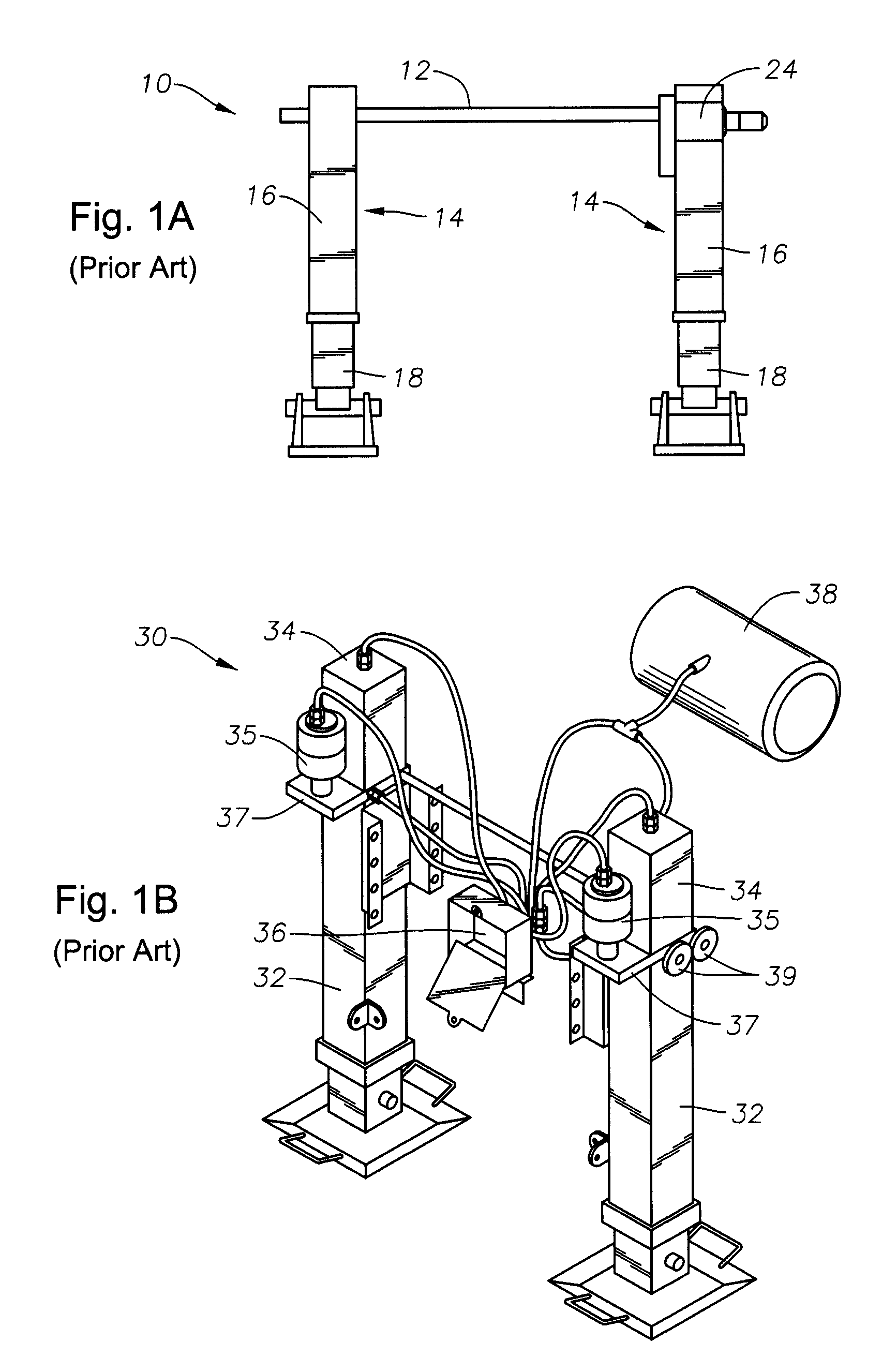
[0021]FIG. 1a depicts a conventional drive-shaft driven landing gear assembly 10 of the prior art. As can be seen in the view of FIG. 1a, the landing gear 10 has a drive shaft 12 which passes through the upper ends of a pair of telescoping legs 14. Each leg 14 has an outer tubular body 16 in which an inner tubular portion 18 is telescopically received. Pivotally mounted feet, wheels or pads 20 attach to the distal end of each inner tubular portion 18. Conventional gear mechanisms (not shown) within outer tubular body 16 cause the inner tubular portion 18 to raise or lower, depending upon the direction of rotation of the drive shaft 12. A gear reduction box 24 may also be provided to assist in transfer of power to the drive shaft 12.

[0022]FIG. 1b depicts a hydraulically driven landing gear assembly 30 of the prior art. As can be seen in the view of FIG. 1b, the landing gear 30 includes a pair of telescoping legs 32, each of which has a hydraulic reservoir 34 disposed on top of its re...


PUM


Abstract

A landing gear system for a trailer is described. The landing gear system includes two jacks, each with a first tubular body in which a second tubular body is telescopically mounted, a hydraulic chamber and a pneumatic chamber. The system includes a hydraulic fluid reservoir, a pneumatic fluid source, a pneumatic manifold in pneumatic fluid communication with the pneumatic source and in pneumatic fluid communication with said hydraulic reservoir and a hydraulic manifold in hydraulic fluid communication with the hydraulic reservoir. Pneumatically operated hydraulic pumps are included, along with a central control mechanism attached to the pneumatic manifold and disposed to simultaneously control pneumatic flow into the pneumatic chambers of the jacks and to pneumatically operated hydraulic pumps. Separate pneumatically operated hydraulic valve are provided to individually control hydraulic flow from the jacks.

Description

BACKGROUND OF THE INVENTION[0001]1. Field of the Invention[0002]The present invention relates to semi-trailer landing gear extension and retraction mechanisms, and more particularly to a pneumatic and hydraulic control mechanism that promotes coordinated extension and retraction of landing gear legs.[0003]2. Description of the Prior Art[0004]Many semi-trailers have front landing gear for support of the front of the trailer when the tractor is detached. Such landing gear generally has two spaced-apart, telescoping or Jack-type landing gear legs which extend downwardly from the bed of the trailer.[0005]Traditionally, each leg is operatively attached to a screw and follower or a rack and pinion gear arrangement which is driven by a landing gear drive shaft extending between the legs. The drive shaft controls extension or retraction of the legs depending on the direction in which it is rotated. Most commonly, a hand operable crank is attached to the landing gear drive shaft. Manual rota...

Claims


Application Information

Patent Timeline
Patent Type & Authority Patents(United States)
IPC IPC(8): B60S9/02
CPCF15B11/072B60S9/12F15B2211/20576
Inventor DANIEL, JEFFREY, K.
Owner DANIEL JEFFREY K
Why Eureka
Try Eureka