Water aeration system and method

Inactive Publication Date: 2014-12-30
UNITED STATES OF AMERICA
View PDF10 Cites 12 Cited by
  • Summary
  • Abstract
  • Description
  • Claims
  • Application Information

AI Technical Summary

Problems solved by technology

The system is structured so that air is directed to the sparger and the sparger emits the air into the water in the conduit's outlet side, thereby aerating the water and creating a hydrostatic pressure imbalance between the inlet side and the outlet side of the conduit.
The pressure im

Method used


Image

  • Water aeration system and method
  • Water aeration system and method

Examples


example

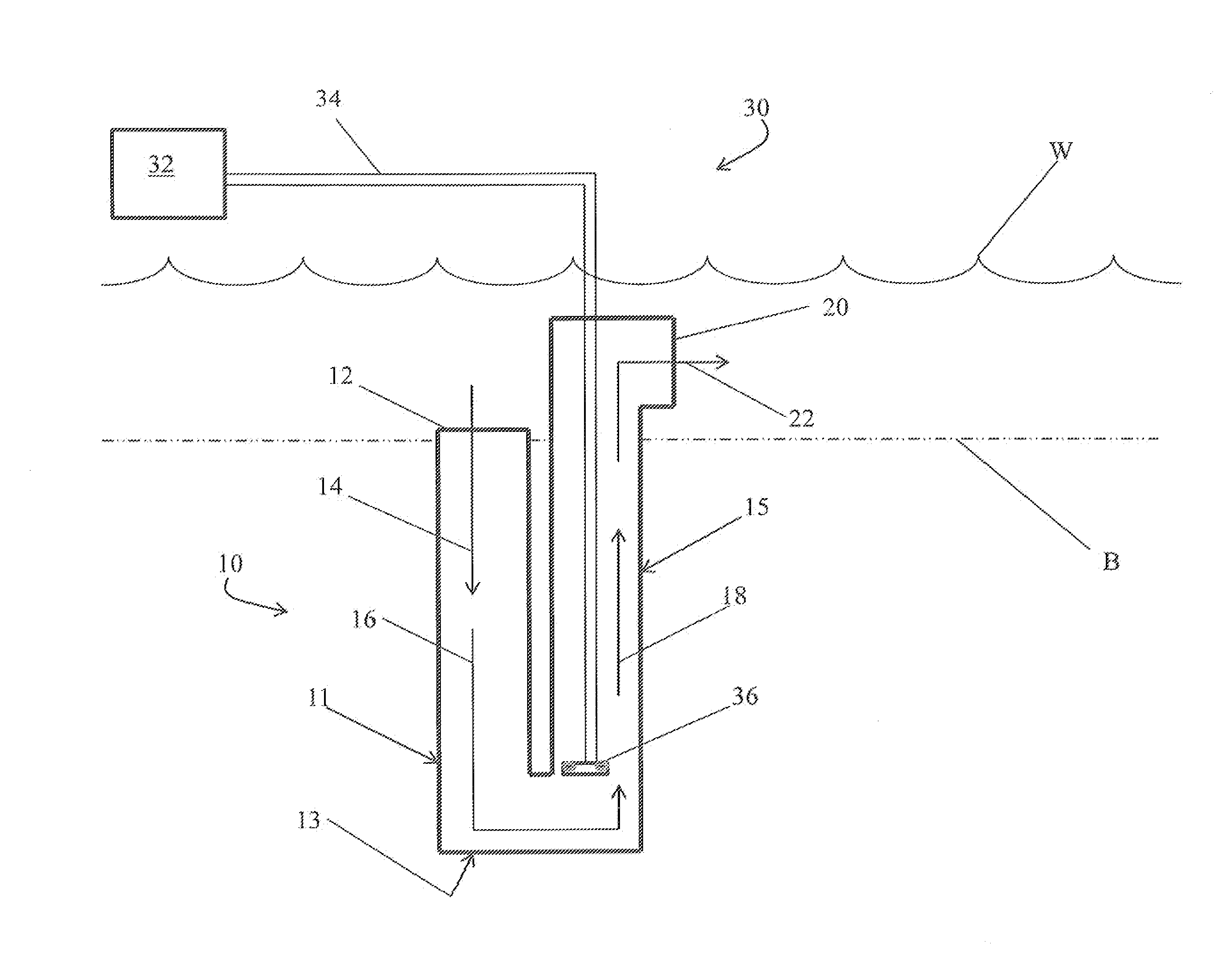
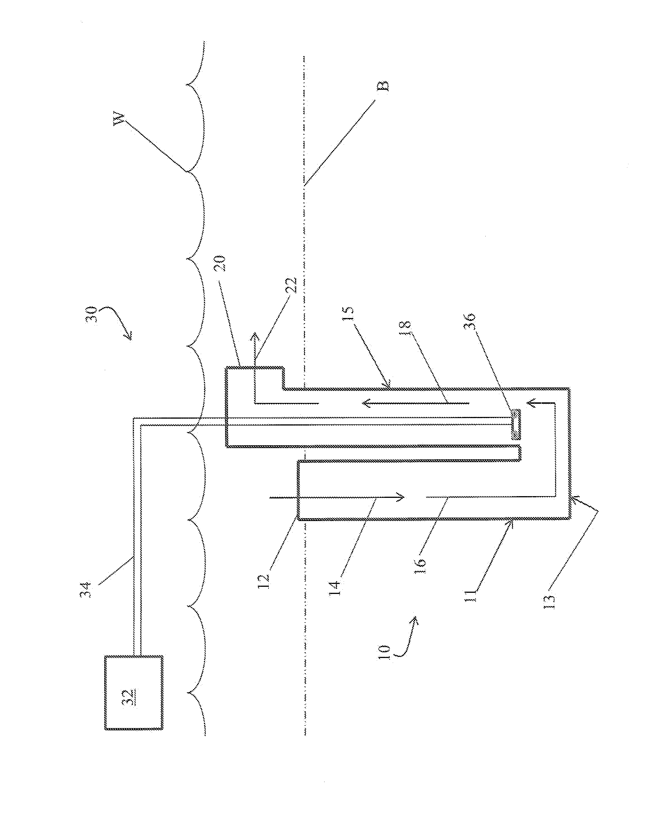
[0016]The inventors designed and tested a prototype of the current invention that was generally designed as described supra. The inlet of the u-tube conduit was positioned at approximately the bottom of the aquaculture pond, and the outlet side of the conduit extended upwardly to about the water's surface. The pond was approximately 1.2 meters deep.

[0017]The u-tube conduit was constructed of 0.9 meter diameter galvanized, corrugated, culvert pipe. A high pressure blower / compressor (positioned on the pond bank) directed pressurized air through an air supply line to the air diffusing sparger assembly positioned near the base of the outlet side of the conduit. The sparger was positioned 6.1 meters below the water surface. The prototype blower comprised a Roots 42 URAI rotary positive displacement blower. The air supply line extended vertically down the outlet side of the conduit to the sparger.

[0018]The sparger emitted the pressurized air in a uniform radial pattern. Air from the sparg...


PUM

PropertyMeasurementUnit
Diameteraaaaaaaaaa
Lengthaaaaaaaaaa
Densityaaaaaaaaaa

Abstract

The aquaculture pond aeration system is essentially comprised of a “u” shaped conduit that extends below the pond bottom. A sparger assembly is positioned below the pond bottom in the outlet side of the conduit. The sparger emits air into the outlet side of the conduit thereby aerating the water and causing a hydrostatic pressure imbalance between the inlet side and the outlet side of the conduit. The pressure imbalance causes the pond water to circulate through the conduit and thereby aerate the aquaculture pond.

Description

FIELD OF THE INVENTION[0001]The present invention relates to a method and apparatus for aerating pond water. Specifically, the invention relates to a method and apparatus for aerating aquaculture ponds primarily used to raise catfish.BACKGROUND OF THE INVENTION[0002]Catfish farming is the largest segment of aquaculture in the US. Catfish are primarily cultured in watershed ponds and are harvested by seining. Despite land and labor costs, pond production can be profitable if water quality is prudently managed. When pond dissolved oxygen (DO) concentrations are low (<2-3 mg / L), the ponds must be aerated to ensure the health of the fish. Aeration is the principal management tool that allows growers to achieve higher feeding rates, increased production, and decreased cost per unit fish produced. US Department of Agriculture research shows that feed conversion ratio (FCR) can be significantly improved by raising the DO concentration above 3.0 mg / L (although catfish can survive at subs...

Claims


Application Information

Patent Timeline
IPC IPC(8): A01K61/00A01K63/04B01F3/04
CPCB01F3/04496B01F3/0446A01K61/00A01K63/04A01K63/042B01F3/04517B01F23/232311A01K61/10
Inventor BROWN, TRAVIS W.TORRANS, EUGENE L.
Owner UNITED STATES OF AMERICA
Why Eureka
Try Eureka