Paper-based microfluidic systems
a microfluidic system and microfluidic technology, applied in the field of paper-based microfluidic systems, can solve the problems of large laboratory instruments, inaccessible most current bioanalytical assays, and inability to perform current diagnostic assays,
- Summary
- Abstract
- Description
- Claims
- Application Information
AI Technical Summary
Benefits of technology
Problems solved by technology
Method used
Image

Examples
example 1
Preparation and Use of Paper Microfluidic Device for Analyte Concentration
[0102]Fabricating a Paper Microfluidic Device
[0103]The prototype μ-PADs was fabricated in a two step process (see FIG. 2). The μ-PADs were prepared in a two-step process that involved creating patterns of hydrophobic polymer in paper, and patterning conductive gold pathways onto the paper-based microfluidic devices.
[0104]First, the microfluidic channels were formed in Whatman filter paper 1 using photolithography and SU-8 photoresist, as described previously (Martinez et al., Angew. Chem. Int. Ed., Eng. 46:1318-1320, 2007). Briefly, this process involved embedding SU-8 photoresist into Whatman filter paper 1, drying the paper to remove the cyclopentanone in the SU-8 formula, and then irradiating the paper for around 3.5 min (using a 100 W mercury lamp) through a pattern of black ink printed onto a transparency. The paper was heated at 90° C. for 10 min, soaked in propylene glycol methyl ether acetate (3×5 min)...
example 2
Preparation and Use of Paper Microfluidic Device for Detecting Salt Concentration
[0115]Fabricating a Paper Microfluidic Device
[0116]Microfluidic channels were fabricated in filter paper (Whatman, Inc.) using a process described previously (Martinez et al., Angew. Chem. Int. Ed., Eng. 6:1318-1320, 2007) (see FIG. 5). The patterns for the microfluidic channels were designed on a computer using a layout editor (Clewin, WieWin Inc.) and a photomask was printed from the design using an inkjet printer and a transparency film. The microfluidic channels were patterned in Whatman filter paper 1 using the following process: (i) paper (2.5 cm×2.5 cm×200 μm) was soaked in resist (SU-8 2010, Microchem Inc.), and a rolling pin was used to press excess resist from the paper; (ii) the paper was dried for 10 min at 95° C., the photomask was clamped to the paper by pressing them together as a sandwich between two glass slides that were held together with binder clips, and the paper was exposed to UV ...
example 3
Preparation and Use of Paper Microfluidic Device with Switches and Valves
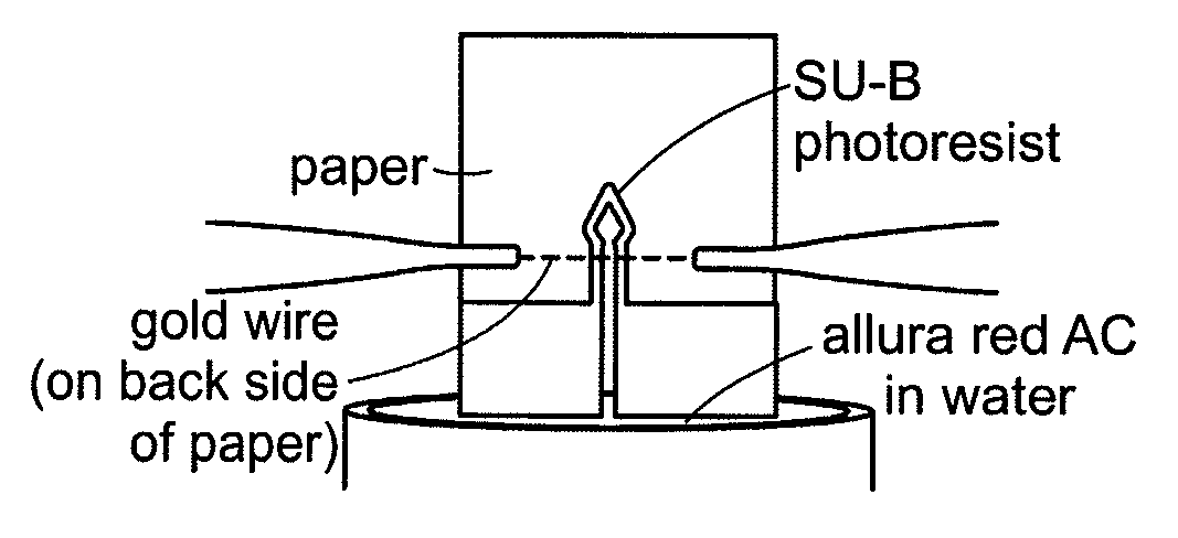
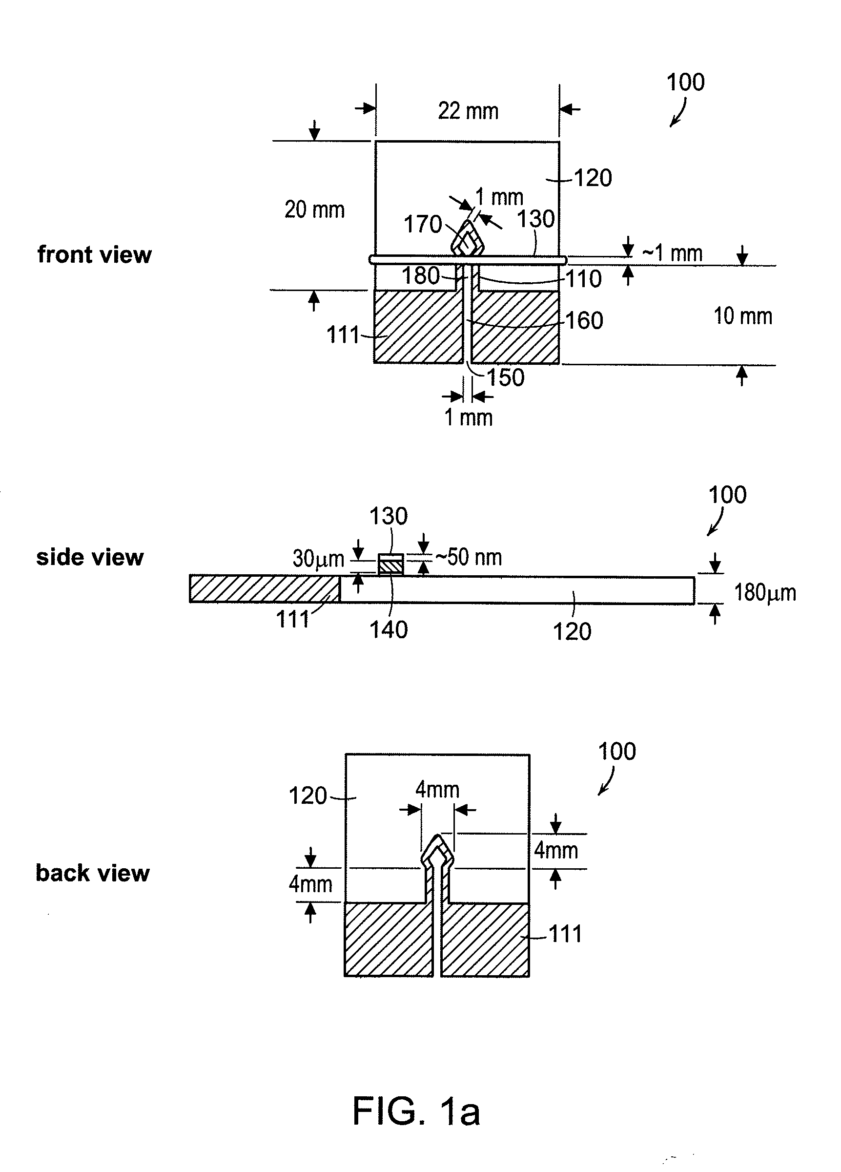
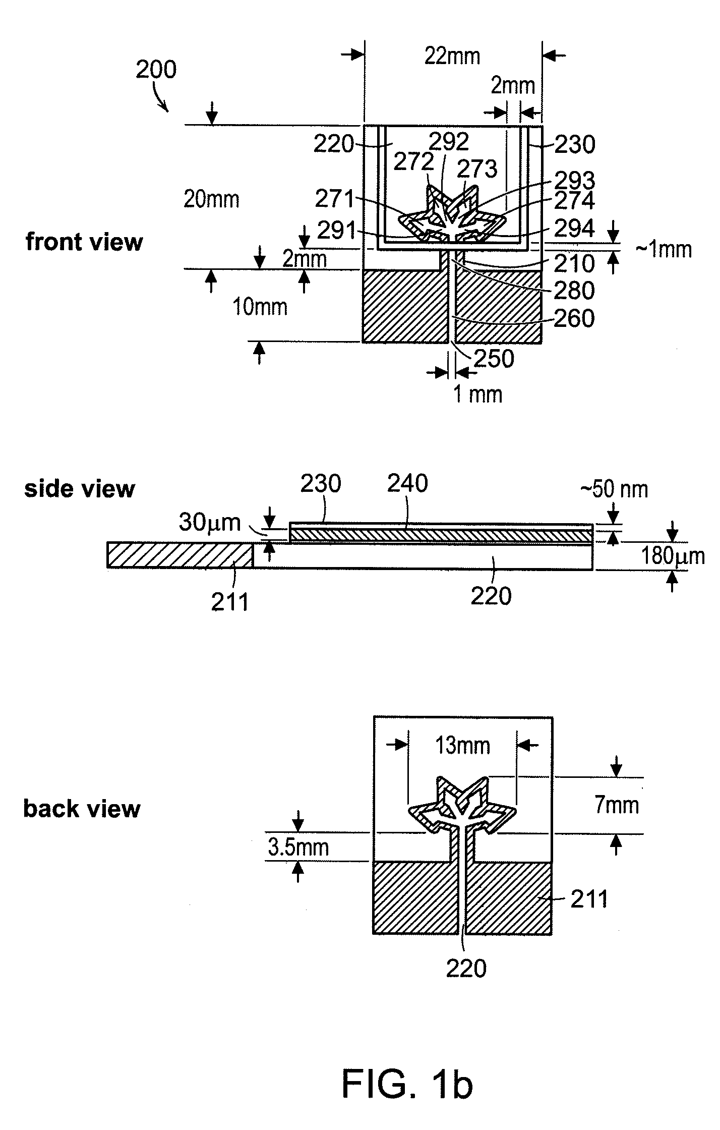
[0128]Fabrication of the Devices
[0129]The microfluidic devices were fabricated using a process that consisted of three general steps: (i) photolithography on a Whatman filter paper 1 using SU-8 photoresist, according to product specifications (MicroChem Corp., Newton, Mass.); (ii) fabrication and attachment of metal-tape wires: 50 nm layer of gold was sputtered (Cressington Model 208HR sputter coater, 60 mA, 50 s sputtering time) onto a matt side of the Scotch tape and attached to the device as a 1-mm-wide strip; and (iii) assembling all the layers of the device.
[0130]Switching the Channels On / Off
[0131]To investigate the switching on / off process in the paper channel, an aqueous solution of red dye (0.05 mM aq. disodium 6-hydroxy-5-((2-methoxy-5-methyl-4-sulfophenyl)azo)-2-naphthalene-sulfonate, allura red) was used to visualize the effectiveness of the device. The solution was conveyed to the central channel of...
PUM
| Property | Measurement | Unit |
|---|---|---|
| resistance | aaaaa | aaaaa |
| temperature | aaaaa | aaaaa |
| resistance | aaaaa | aaaaa |
Abstract
Description
Claims
Application Information
 - R&D
- Intellectual Property
- Life Sciences
- Materials
- Tech Scout
- Unparalleled Data Quality
- Higher Quality Content
- 60% Fewer Hallucinations
Browse by: Latest US Patents, China's latest patents, Technical Efficacy Thesaurus, Application Domain, Technology Topic, Popular Technical Reports.
© 2025 PatSnap. All rights reserved.Legal|Privacy policy|Modern Slavery Act Transparency Statement|Sitemap|About US| Contact US: help@patsnap.com