High efficiency low torque ripple multi-phase permanent magnet machine

a multi-phase permanent magnet machine, low-torque ripple technology, applied in the direction of mechanical energy handling, magnetic circuit rotating parts, magnetic circuit shape/form/construction, etc., can solve the problems of low efficiency, armature effect, excessive heating, and strong “torque ripple” tendencies, and achieve high efficiency and torque ripple. , the effect of improving efficiency

Inactive Publication Date: 2014-12-30
RITTENHOUSE NORMAN P
View PDF69 Cites 21 Cited by
  • Summary
  • Abstract
  • Description
  • Claims
  • Application Information

AI Technical Summary

Benefits of technology

[0007]A primary objective of the present invention is to provide methods, systems and devices for a high efficiency low torque ripple multi-phase permanent magnet machine with a new, unique stator configuration, torque ripple is all but eliminated, efficiency is improved still further, and smoothness is enhanced.
[0020]The rotor-stator structure of can be powered as a variable speed alternating current motor that includes a rotor with an even number of alternating polarity permanent magnet poles, a stator with an odd number of poles, in which each stator pole coil is individually wound and one terminal of each coil is connected to a common neutral, and the other terminal of each coil is connected to a complimentary, timed semiconductor switch of three groups, each group being supplied with one phase of alternating current via an AC buss, to allow the machine to operate as a variable speed AC motor, providing seamless power, free of torque ripple.
[0021]The rotor-stator structure can be powered as a variable speed alternating current motor that includes a rotor with an even number al alternating polarity permanent magnet poles, a stator with an odd number of poles, in which each stator pole coil is individually wound with the coils terminals connected to complimentary, timed semiconductor switches in a bridge configuration, with the individual bridges arranged three groups, each group being supplied with one phase of alternating current via an AC buss, to allow the machine to operate as a variable speed AC motor, providing seamless power, free of torque ripple.

Problems solved by technology

While these motors are cheap to build, they suffer from low efficiency, armature effect, and excessive heating.
While this configuration had higher efficiency, it then displayed strong “torque cogging” tendencies, and was still subject to the efficiency robbing “armature effect”
Other inventors pursued “fractional slot” configurations of the original “squirrel cage” design, which lowered torque ripple, but at a loss of overall efficiency.
Some of their “fractional” stators slots actually rob power and may be considered parasitic “drones”, because they oppose the direction of rotation.

Method used


Image

  • High efficiency low torque ripple multi-phase permanent magnet machine
  • High efficiency low torque ripple multi-phase permanent magnet machine
  • High efficiency low torque ripple multi-phase permanent magnet machine

Examples


Embodiment Construction

[0048]Before explaining the disclosed embodiments of the present invention in detail it is to be understood that the invention is not limited in its application to the details of the particular arrangements shown since the invention is capable of other embodiments. Also, the terminology used herein is for the purpose of description and not of limitation.

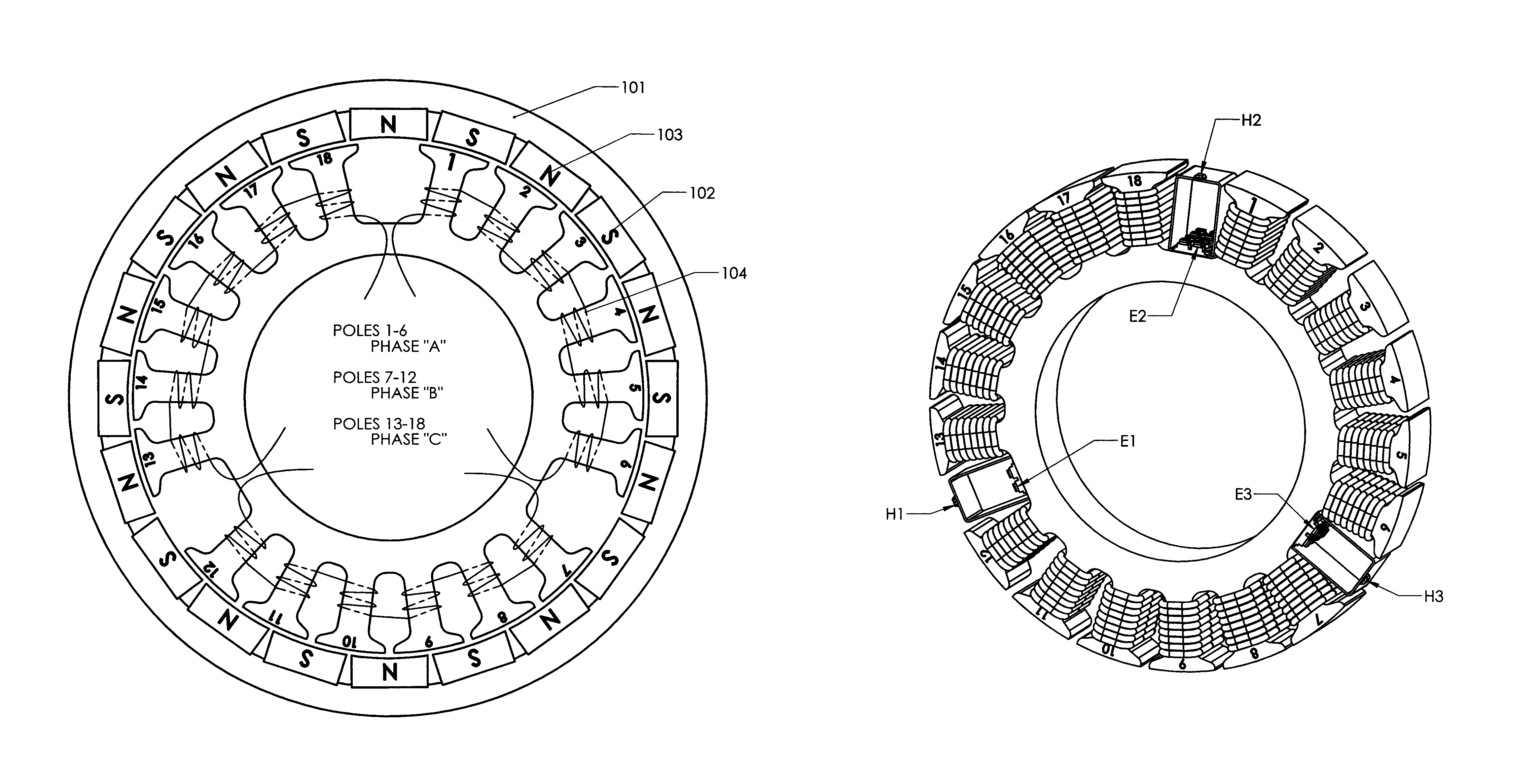
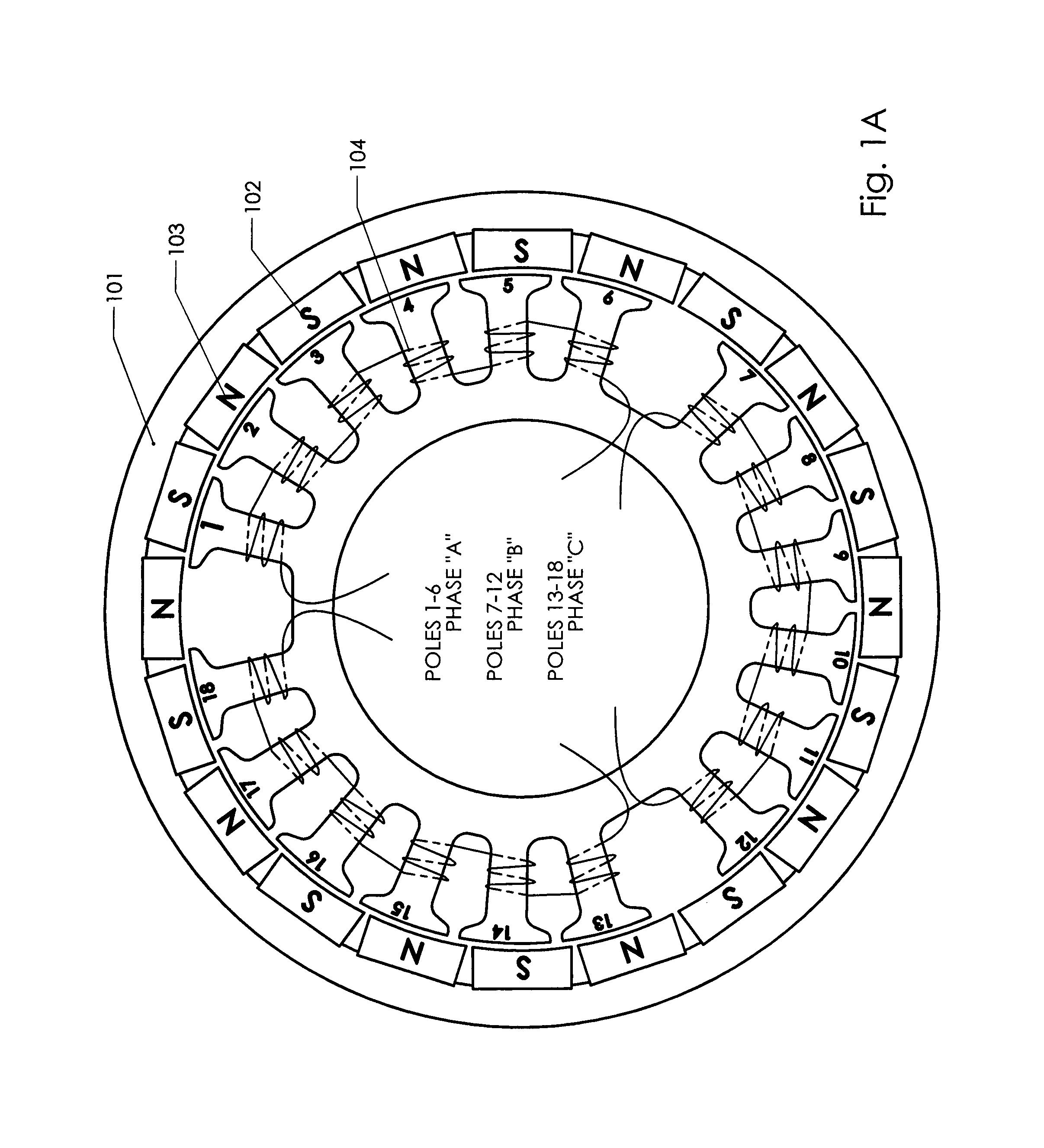
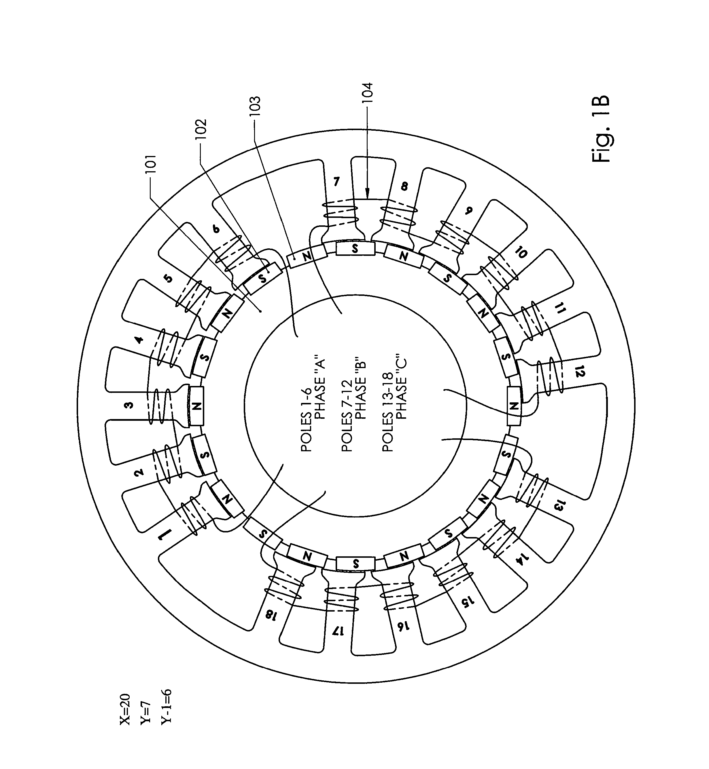
[0049]The following is a list of reference numerals used in the description and the drawings to identify components:[0050]101 rotating rotor magnet drum[0051]102 South Pole Permanent Magnet[0052]103 North Pole Permanent Magnet[0053]104 stator phase winding[0054]106 hub[0055]200 bicycle wheel[0056]201 tire[0057]202 axel[0058]204 bearing[0059]206 non-rotating hub[0060]300 propeller[0061]302 axel[0062]304 bearing[0063]306 non-rotating hub[0064]810A stator poles phase A[0065]810B stator poles phase B[0066]810C stator poles phase C[0067]820 non-metallic hub[0068]830A conductors[0069]830B conductors[0070]830C conductors[0071]901 rotor drum...


PUM


Abstract

An electrically driven motor, an electrical generator, a rotating electrical machine and method of operating, that includes a rotating rotor having an even number of alternating polarity permanent magnet poles and a stator with an odd number of evenly spaced alternating magnetic polarity electromagnetic poles divided into an odd number of equal stator phase groups with a magnetically unbalanced orphan, pole from each stator phase group removed without re-spacing the remaining stator poles to produce a gap between stator phase groups that is greater than the spacing between adjacent poles in each stator phase group. The rotor can be a rotating external rotor or a stationary internal rotor and the stator can be a stationary interior stator or a rotating exterior stator.

Description

FIELD OF THE INVENTION[0001]This invention relates to motors and generators and, in particular, to methods, systems and devices and machines for a high efficiency low torque ripple multi-phase permanent magnet motor and / or generator having a rotor-stator structure.BACKGROUND AND PRIOR ART[0002]Most multi-phase motor designs are derived from those originated by Nicola Tesla, and are sometimes described as “squirrel cage” or “rotating field” motors. While these motors are cheap to build, they suffer from low efficiency, armature effect, and excessive heating.[0003]Earlier conversions of squirrel cage motors to permanent magnet merely replaced the rotor iron laminations with permanent magnets. While this configuration had higher efficiency, it then displayed strong “torque cogging” tendencies, and was still subject to the efficiency robbing “armature effect”[0004]Other inventors pursued “fractional slot” configurations of the original “squirrel cage” design, which lowered torque ripple...

Claims


Application Information

Patent Timeline
Patent Type & Authority Patents(United States)
IPC IPC(8): H02K21/12H02K1/14H02K9/08H02K21/22H02K21/00H02K1/27H02K11/00H02K9/20
CPCH02K1/2786H02K1/148H02K9/08H02K1/278H02K1/146H02K11/0073H02K11/0021H02K9/20H02K1/187H02K7/14H02K16/00H02K21/16H02K21/222H02K29/03H02K2213/03H02K2213/12H02P9/009H02P9/02
Inventor RITTENHOUSE, NORMAN, P
Owner RITTENHOUSE NORMAN P
Why Eureka
Try Eureka