Firearm sight

a technology for firearms and sights, applied in the direction of sighting devices, weapons, weapon components, etc., can solve the problems of not being able to accurately hit targets, not being able to move targets or shoot quickly, and taking a large amount of practice to achieve the effect of accurately hitting targets, preventing accidental shooting, and not adversely affecting weapon balan

Active Publication Date: 2015-01-06
ANDERSON NORMAN L
View PDF21 Cites 18 Cited by
  • Summary
  • Abstract
  • Description
  • Claims
  • Application Information

AI Technical Summary

Benefits of technology

[0010]The device uses a transparent, optically clear lens which removably holds a fiber optic rod. The lens is removably fixed inside a metal ring, and allows the user to see a visibly bright sighting point without disrupting the larger field of view and visual of the entire target. The ring is preferably threaded into a base to allow for adjustments to be made to zero the rifle and may be locked in position by one or more ball-detents using thumbscrews to secure. The ring, preferably, is symmetrical to appear identical from either side. The threaded base for mounting of the ring is subject to barrel dimensions and diameters based on the firearm. The weight of the sight is negligible and does not adversely affect weapon balance or hinder proper aiming.

Problems solved by technology

Yet if the sights on the firearm are not effective, the firearm will not accurately hit targets.
This takes a large amount of practice to do properly and even then this sighting process takes time and hence does not lend itself well to shooting at moving targets or to shooting rapidly.
One problem associated with this arrangement is the post type front sight covers the target, obscures the field of view, and confuses point of aim.
However, the telescopic sight requires a mount for mounting the telescope to the firearm and a telescope mount creates other problems.
The telescope and its mount obviously add weight to the firearm, but more importantly it raises the line of sight higher and farther away from the firearm barrel bore axis than with standard iron sights.
This causes several problems.
In many cases this will mean that the standard or factory stock will have to be replaced and the shooter incurs the associated expense and inconvenience.
In addition, for both rifles and shotguns and other such small arms firearms, the higher line of sight above the bore axis means that it is more difficult to adjust the sight for shooting at a variety of ranges with one sight setting or even with minor adjustments.
Also, the higher line of sight means that movement or rotation of the rifle, shotgun, or other small firearm will result in greater inaccuracy than would be the case if iron sights were used.
Another problem with a telescopic sight is that it may strike the eye of the shooter when the firearm recoils if it is not properly mounted for that shooter.
While use of a telescopic sight magnifies the view of the target, it also reduces the shooter's peripheral vision.
As with any battery-operated device, these types of sights are susceptible to loss of power, whether due to expiration of battery life, damage, or conventional wear-and-tear.
Unpowered, these types of sights are of limited or no use.

Method used


Image

  • Firearm sight
  • Firearm sight
  • Firearm sight

Examples


Embodiment Construction

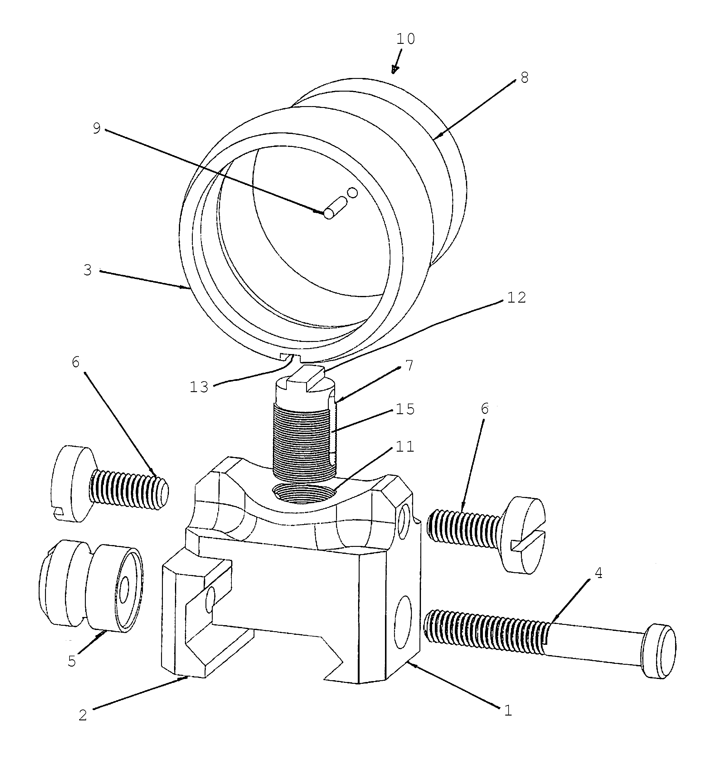
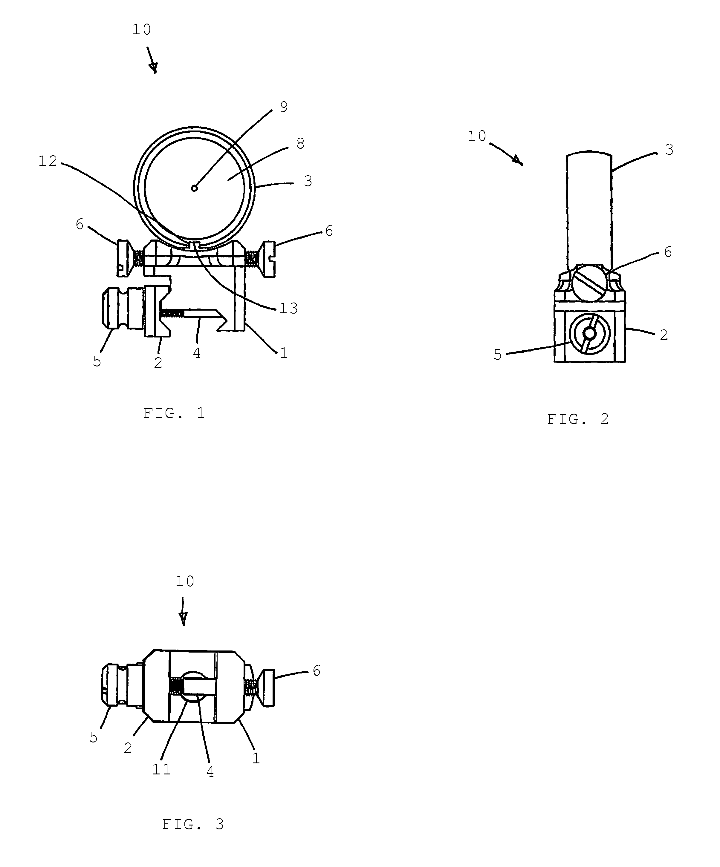
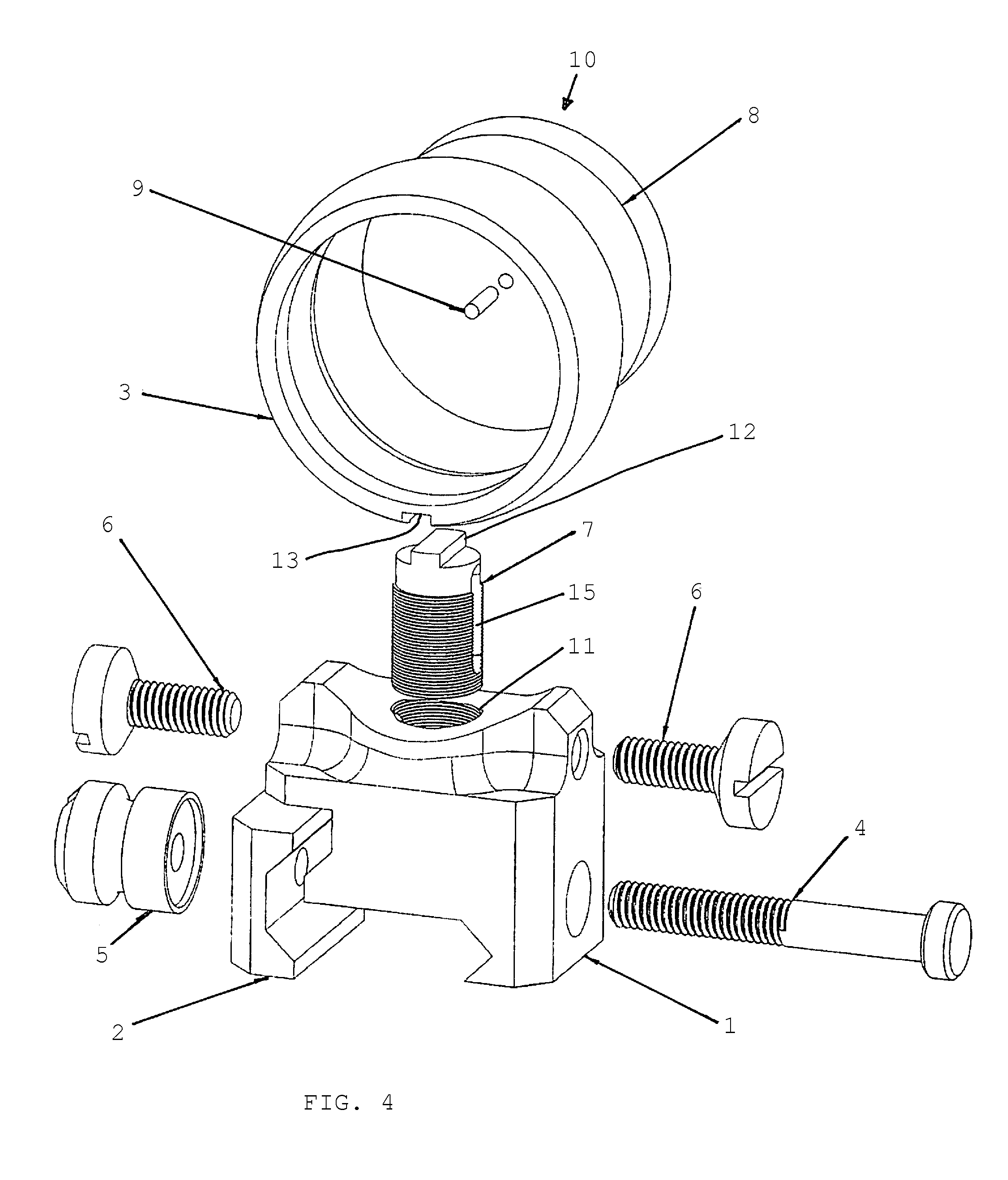
[0016]The present invention generally relates to a device to be used as a sight or as forward reference point in an alignment or targeting system on a firearm barrel, whether rifled or smoothbore. The sight 10 uses a support ring 3 to hold removably an optically clear, transparent lens 8, which holds a fiber optic member or rod 9. In other words, the fiber optic member 9 is embedded within an annular lens 8, which is surrounded by an annular ring 3; the lens 8 is removable. The lens 8 has identical front and back faces and is generally flat, and is optically neutral. The lens need not be perfectly flat, it can have slight curvature or variation. The lens 8 can be curved to magnify or refract light, but flat and optically neutral is preferred. In an alternate embodiment, the fiber optic member 9 is also removable. This arrangement allows the user to see a visibly bright sighting point while providing a larger field of view and a visual of the entire target. The ring 3 is symmetrical ...


PUM


Abstract

A firearm sight comprising a generally circular sight support ring surrounding and removably holding an optically clear generally circular lens, said lens having a cylindrical shape, front and back faces, a diameter greater than the thickness of the lens, and a scintillating fiber optic member centrally embedded within said circular lens, a means for mounting said circular sight support ring to a firearm, and a means of adjusting said circular support ring in relation to said means for mounting said ring to a firearm.

Description

BACKGROUND OF THE INVENTION[0001]The present invention relates to an aiming device, or sight, for a firearm. Specifically, it describes a simple, effective, passively illuminated, non-telescopic sight requiring no power source.[0002]Proper sights on firearms are essential for accurate shooting. The firearm, such as a rifle or shotgun, can be inherently very accurate due to its design and manufacture. Yet if the sights on the firearm are not effective, the firearm will not accurately hit targets. It is important to bear in mind, of course, that some sights are easier to use by some shooters than others.[0003]Typically, firearms will have both a front sight, located on the firearm barrel near the muzzle of the barrel, and a rear sight, located near the rear or breech end of the barrel or on the receiver or breech portion of the firearm. These sights are commonly referred to as iron sights. In order to shoot the firearm accurately, the shooter must line up the front sight and the rear ...

Claims


Application Information

Patent Timeline
Patent Type & Authority Patents(United States)
IPC IPC(8): F41G1/00F41G1/08F41G1/12F41G1/16F41G1/34
CPCF41G1/345F41G1/08F41G1/12F41G1/16
Inventor ANDERSON, NORMAN L.
Owner ANDERSON NORMAN L
Why Eureka
Try Eureka