Method and apparatus for variable valve actuation

a variable valve and valve actuator technology, applied in the direction of machines/engines, output power, electric control, etc., can solve the problems of reduced air-to-fuel ratio of in-cylinder mixture, pre-detonation or an unacceptable high internal engine cylinder pressure, poor acceleration, etc., to reduce turbolag and increase turbine acceleration

Active Publication Date: 2015-01-06
VOLVO LASTVAGNAR AB
View PDF19 Cites 2 Cited by
  • Summary
  • Abstract
  • Description
  • Claims
  • Application Information

AI Technical Summary

Benefits of technology

[0002]Turbochargers are well known and widely used with combustion engines for purpose of increasing power output, decreasing fuel consumption and emissions, and compensating for air density loss at high altitudes. Generally, turbochargers supply an increased charge air supply for the combustion process than can otherwise be induced through natural aspiration by utilizing exhaust gas energy to drive an air compressor. This increased air supply allows more fuel to be burned, thereby increasing power and output not otherwise obtainable from an engine having a given cylinder displacement under natural aspiration conditions. Variable geometry turbochargers (VGTs) allow the intake airflow to be optimized over a range of engine speeds. This may be accomplished by changing the angle of the inlet guide vanes on the turbine stator. An optimal position for the inlet guide vanes is determined from a combination of desired torque response, fuel economy, and emission requirement.
[0029]According to yet another aspect of the present invention it is provided an apparatus for reducing turbolag in a turbocharged internal combustion engine comprising an inlet manifold, an exhaust manifold, an exhaust gas recirculation (EGR) valve and a Variable Geometry Turbine (VGT) turbo unit. Said apparatus comprising: means for demanding torque for shifting the internal combustion engine from a stationary engine mode to a transient engine mode; means for closing the EGR valve at a positive pressure difference during said transient engine mode; means for repositioning guide vanes of the VGT turbo unit from a first position when in said stationary engine mode to a second position at said positive pressure difference during said transient engine mode; means for increasing a duration of overlapping of at least one inlet valve and at least one outlet valve provided in a cylinder head of said internal combustion engine from a first duration when in said stationary engine mode to a second duration at said positive pressure difference during said transient engine mode for increasing the amount of air flowing from the inlet manifold to the exhaust manifold and thereby increasing acceleration of a turbine of said VGT turbo unit.BRIEF DESCRIPTION OF THE DRAWINGS

Problems solved by technology

On the other hand, the recirculated exhaust gas displaces fresh air and reduces the air-to-fuel ratio of the in-cylinder mixture.
Typically, the waste gate is set to open at a pressure below which undesirable predetonation or an unacceptable high internal engine cylinder pressure is generated.
A particular problem with turbocharged diesel engines is poor acceleration, particularly from idle or low engine speeds.
This “turbo-lag” is due to the time delay associated with filling the intake manifold with enough fresh air to support the amount of fuel required to satisfy the operator's torque demand.
To meet this requirement, however, the delivered fuel often must be limited as a function of the available air in order to maintain the air-to fuel ratio above the threshold at which visible smoke occurs.
The rate at which the air supply can be increased is limited by the dynamics of the turbocharger and the transport delay between the turbocharger compressor and the intake manifold of the engine.

Method used


Image

  • Method and apparatus for variable valve actuation
  • Method and apparatus for variable valve actuation
  • Method and apparatus for variable valve actuation

Examples


Embodiment Construction

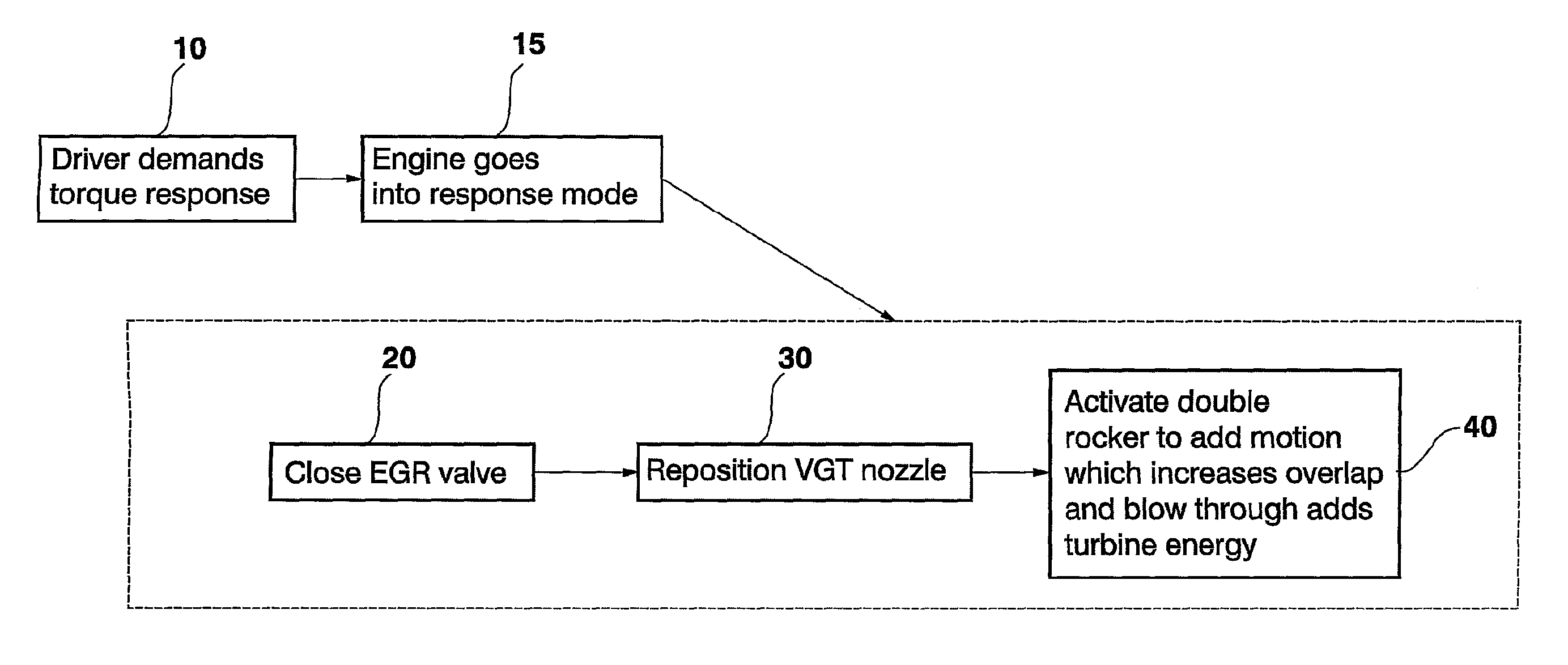
[0038]FIG. 1 illustrates schematically a flowchart of an example embodiment of a method for reducing turbolag in a turbocharged internal combustion engine. As seen in FIG. 6, the engine 1 comprises an inlet manifold 2, an exhaust manifold 3, an exhaust gas recirculation (EGR) line 4 between the exhaust manifold and the inlet manifold and including an EGR valve 5 and a Variable Geometry Turbine (VGT) turbo unit 6.

[0039]Said method for reducing turbolag comprising a first step 10 of demanding torque for shifting the internal combustion engine from a stationary engine mode to a transient engine mode. The demanding of torque may be performed by depressing an accelerator pedal by the driver. When the driver demands torque by depressing the accelerator pedal the engine goes into a response mode or a transient engine mode 15.

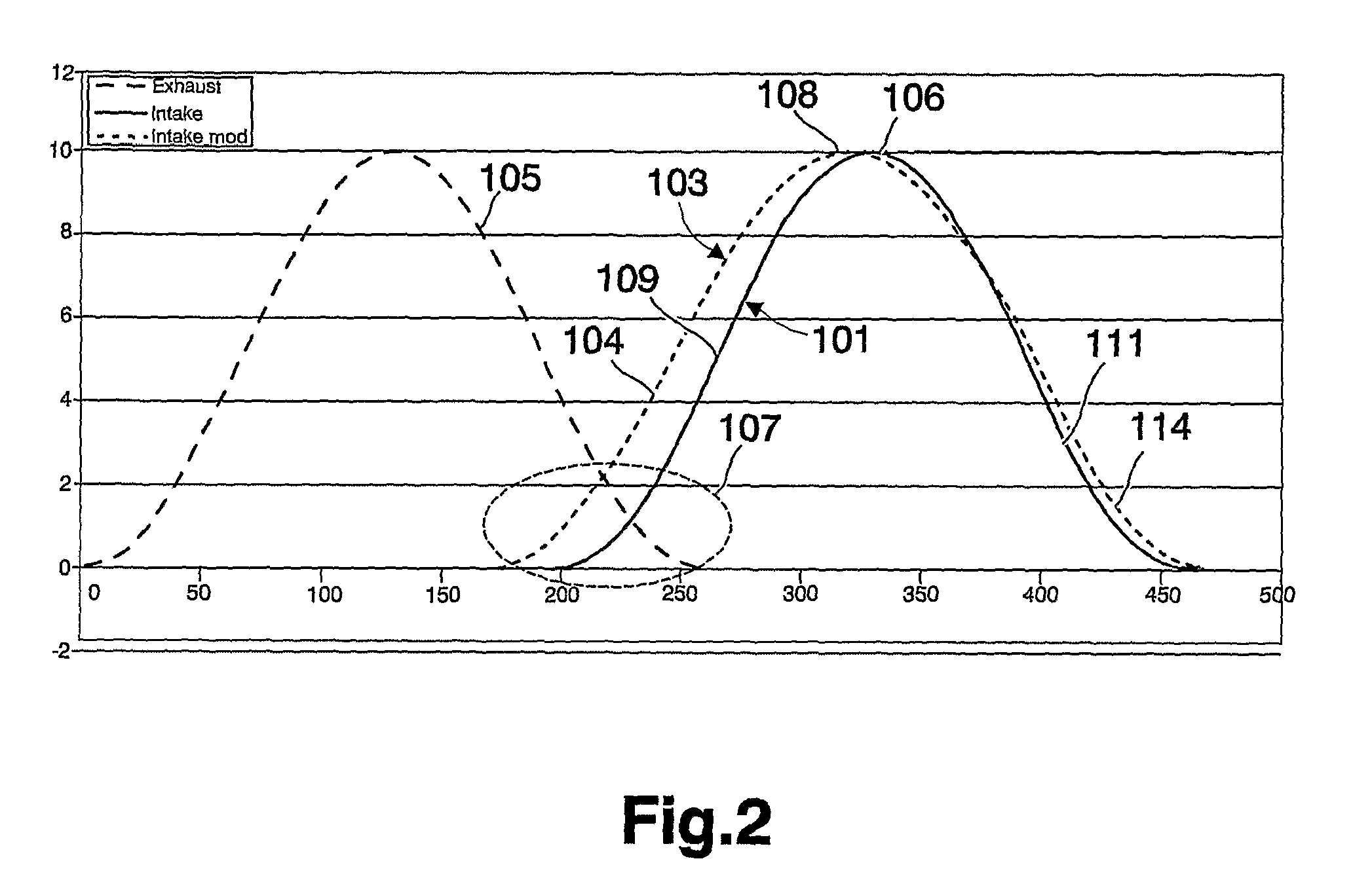
[0040]The transient engine mode may be characterized by a higher boost pressure than the exhaust pressure, i.e., the pressure upstream an inlet valve of the internal c...


PUM


Abstract

A method for reducing turbolag in a turbocharged internal combustion engine includes demanding torque for shifting the internal combustion engine from a stationary engine mode to a transient engine mode, closing an exhaust gas recirculation (EGR) valve during the transient engine mode, repositioning guide vanes of a Variable Geometry Turbine (VGT) turbo unit from a first position when in the stationary engine mode to a second position when in the transient engine mode, increasing a duration of overlapping of at least one inlet valve and at least one outlet valve provided in a cylinder head of the internal combustion engine from as first duration when in the stationary mode to a second duration when in the transient mode for increasing the amount of air flowing from an inlet manifold to an exhaust manifold and thereby increasing acceleration of a turbine of the VGT turbo unit.

Description

BACKGROUND AND SUMMARY[0001]The present invention relates to a method and an apparatus for an internal combustion engine.[0002]Turbochargers are well known and widely used with combustion engines for purpose of increasing power output, decreasing fuel consumption and emissions, and compensating for air density loss at high altitudes. Generally, turbochargers supply an increased charge air supply for the combustion process than can otherwise be induced through natural aspiration by utilizing exhaust gas energy to drive an air compressor. This increased air supply allows more fuel to be burned, thereby increasing power and output not otherwise obtainable from an engine having a given cylinder displacement under natural aspiration conditions. Variable geometry turbochargers (VGTs) allow the intake airflow to be optimized over a range of engine speeds. This may be accomplished by changing the angle of the inlet guide vanes on the turbine stator. An optimal position for the inlet guide v...

Claims


Application Information

Patent Timeline
Patent Type & Authority Patents(United States)
IPC IPC(8): F02B33/44F02P13/00F02B47/08F01L1/18F01L13/00F02D13/02F02D41/00F02D41/10
CPCF02D13/0265F01L1/181F01L13/0015F01L13/0036F02D41/0007F02D41/0055F02D41/10F02D2041/001Y02T10/144Y02T10/47Y02T10/18Y02T10/12Y02T10/40
Inventor NORDSTRAND, ANDREASZANDER, LENNARTH
Owner VOLVO LASTVAGNAR AB
Why Eureka
Try Eureka