Device for controlling a gas flow, an exhaust aftertreatment system and a system for propelling a vehicle

a technology of gas flow and control device, which is applied in the direction of radial flow pumps, mechanical equipment, machines/engines, etc., can solve the problems of substantially the same leakage between, damage to the vanes, etc., and achieve the reduction of the risk of different turbocharger units acting differently, the effect of robust and accurate control of the individual turbocharger units and the reduction of wear between the vanes during operation

Active Publication Date: 2018-05-01
VOLVO LASTVAGNAR AB
View PDF36 Cites 2 Cited by
  • Summary
  • Abstract
  • Description
  • Claims
  • Application Information

AI Technical Summary

Benefits of technology

[0001]The present invention relates to a device for controlling a gas flow and more specifically to a variable geometry turbine for a turbocharging unit for an internal combustion engine. The invention further relates to application of the device in an exhaust aftertreatment system for controlling the function of an exhaust aftertreatment unit in the exhaust aftertreatment system. One application is to achieve a high engine braking performance.
[0002]Turbochargers are well known and widely used with internal combustion engines for purpose of increasing power output, decreasing fuel consumption and emissions, and compensating for air density loss at high altitudes. Generally, turbochargers supply an increased charge air supply for the combustion process than can otherwise be induced through natural aspiration by utilizing exhaust gas energy to drive an air compressor. This increased air supply allows more fuel to be burned, thereby increasing power and output not otherwise obtainable from an engine having a given cylinder displacement under natural aspiration conditions.

Problems solved by technology

Closing of the vanes may however result in damage to the vanes.
This design of the vanes will result in that substantially the same leakage between two adjacent vanes is achieved when the vanes are in said first mutual end state.

Method used


Image

  • Device for controlling a gas flow, an exhaust aftertreatment system and a system for propelling a vehicle
  • Device for controlling a gas flow, an exhaust aftertreatment system and a system for propelling a vehicle
  • Device for controlling a gas flow, an exhaust aftertreatment system and a system for propelling a vehicle

Examples


Embodiment Construction

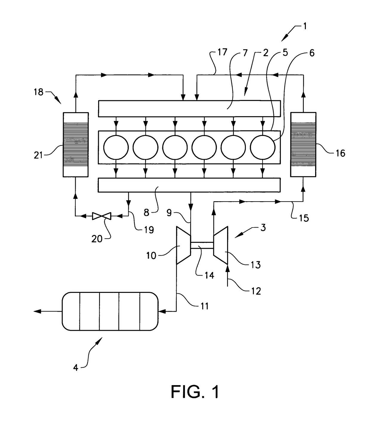
[0022]FIG. 1 schematically shows a system 1 for propelling a vehicle, preferably a heavy-duty commercial vehicle such as a truck, bus or construction machine, comprising an internal combustion engine 2 in the form of a diesel engine, a turbocharger unit 3 and a gas aftertreatment device 4.

[0023]The engine comprises an engine block 5 with six cylinders 6 which communicate in a conventional manner with an inlet manifold 7 and an exhaust manifold 8. The exhaust manifold 8 receives exhaust gases from the engine cylinders. The exhaust gases are led through a pipe 9 (or turbine housing) from the exhaust manifold 8 to a turbine 10 in the turbocharger unit 3 and further via a pipe 11 from the turbine 10 to the gas aftertreatment device.

[0024]Filtered inlet air is admitted to the engine through a pipe 12 and led to a compressor 13 of the turbocharger unit 3. The compressor 13 is mounted on a common shaft 14 with the turbine 10. During operation, the compressor 13 is driven by the turbine 10....


PUM


Abstract

A device for controlling a gas flow through a passage includes a plurality of pivotable gas flow control vanes. The pivot axes of a first and a second adjacent vane are spaced so that a trailing edge of the first vane overlaps a leading edge of the second vane when the first and second adjacent vanes are positioned in a first mutual end state for substantially restricting the gas flow through the passage. The second vane includes a recess with such a shape that the trailing edge of the first vane is at least partly received in the recess when the first and second adjacent vanes are positioned in the first mutual end state.

Description

BACKGROUND AND SUMMARY[0001]The present invention relates to a device for controlling a gas flow and more specifically to a variable geometry turbine for a turbocharging unit for an internal combustion engine. The invention further relates to application of the device in an exhaust aftertreatment system for controlling the function of an exhaust aftertreatment unit in the exhaust aftertreatment system. One application is to achieve a high engine braking performance.[0002]Turbochargers are well known and widely used with internal combustion engines for purpose of increasing power output, decreasing fuel consumption and emissions, and compensating for air density loss at high altitudes. Generally, turbochargers supply an increased charge air supply for the combustion process than can otherwise be induced through natural aspiration by utilizing exhaust gas energy to drive an air compressor. This increased air supply allows more fuel to be burned, thereby increasing power and output not...

Claims


Application Information

Patent Timeline
Patent Type & Authority Patents(United States)
IPC IPC(8): F01D17/14F04D27/00F01D17/16F04D27/02F02B47/08F04D17/10
CPCF04D27/002F01D17/165F02B47/08F04D17/10F05D2250/70F05D2220/40F05D2240/121
Inventor KRAUSCHE, SEBASTIANSUNDIN, LARS
Owner VOLVO LASTVAGNAR AB
Why Eureka
Try Eureka