Method and apparatus for controlling turbine efficiency

Inactive Publication Date: 2012-06-28
VOLVO LASTVAGNAR AB
View PDF6 Cites 4 Cited by
  • Summary
  • Abstract
  • Description
  • Claims
  • Application Information

AI Technical Summary

Benefits of technology

[0002]Turbochargers are well known and widely used with combustion engines for purpose of increasing power output, decreasing fuel consumption and emissions, and compensating for air density loss at high altitudes. Generally, turbochargers supply an increased charge air supply for the combustion process than can otherwise be induced through natural aspiration by utilizing exhaust gas energy to drive an air compressor. This increased air supply allows more fuel to be burned, thereby increasing power and output not otherwise obtainable from an engine having a given cylinder displacement under natural aspiration conditions. Variable geometry turbochargers (VGTs) allow the intake airflow to be optimized over a range of engine speeds. This may be accomplished by changing the angle of the inlet guide vanes on the turbine stator. An optimal position for the inlet guide vanes is determined from a combination of desired torque response, fuel economy, and emission requirement.
[0027]An advantage of this embodiment is that it gives sufficient flow of gas at the same time as it may cool down the turbo unit since such flow of gas has a substantially lower temperature than the exhaust gases.

Problems solved by technology

On the other hand, the recirculated exhaust gas displaces fresh air and reduces the air-to-fuel ratio of the in-cylinder mixture.
This means that, if the turbo efficiency is too high, the boost pressure and other limits on the engine, e.g. turbo speed, max cylinder pressure, compressor temperature, will be too high when the VGT position is decreased to achieve sufficient EGR drive pressure.
A consequence of this is a fuel and emission penalty due to increased gas exchange losses and lower lambda in areas where the limits are not reached which may be a problem.
The EGR control range will also be limited and sets a limit to the maximum power / torque achievable from the engine which also may be a problem.

Method used


Image

  • Method and apparatus for controlling turbine efficiency
  • Method and apparatus for controlling turbine efficiency
  • Method and apparatus for controlling turbine efficiency

Examples


Embodiment Construction

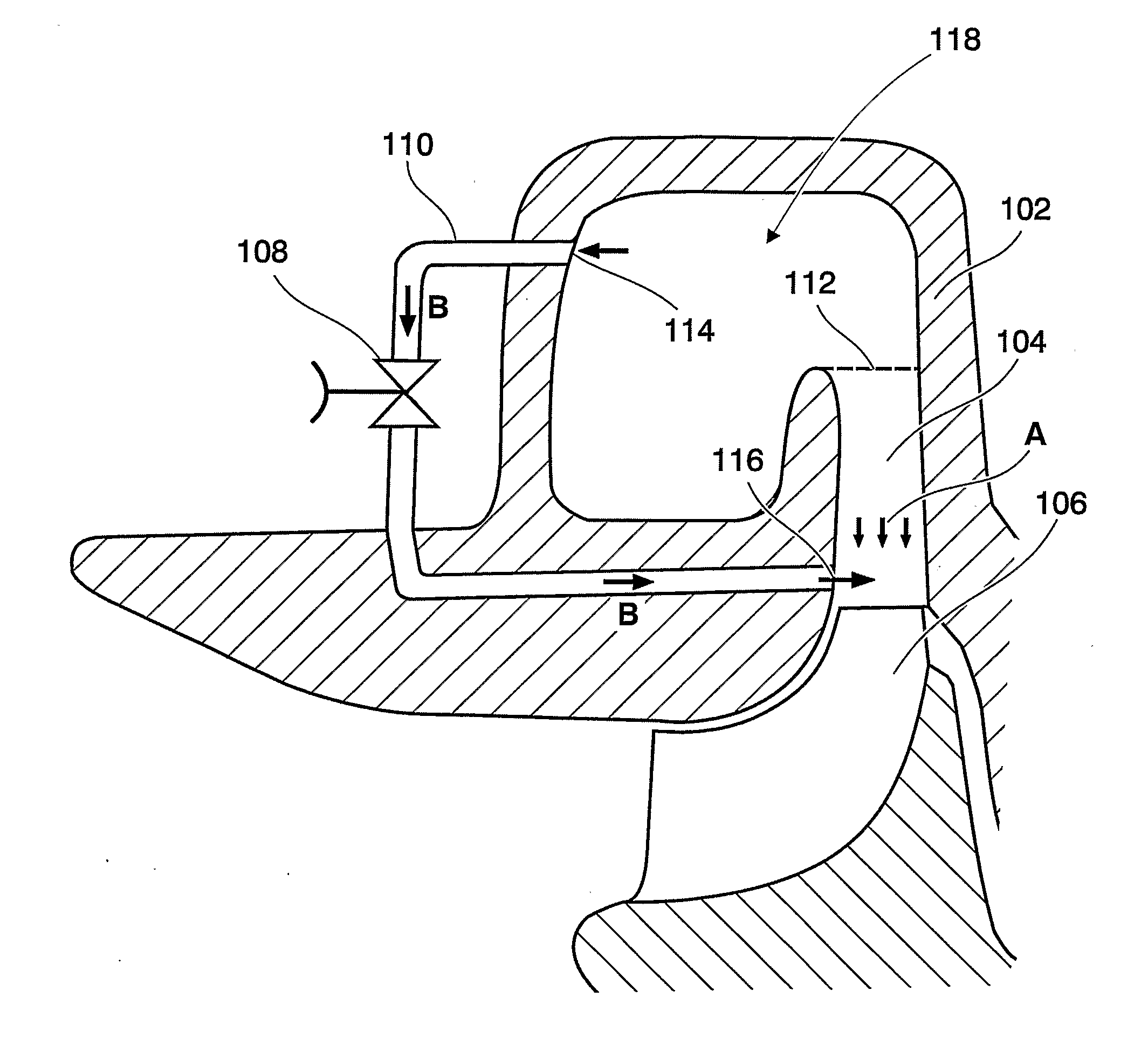
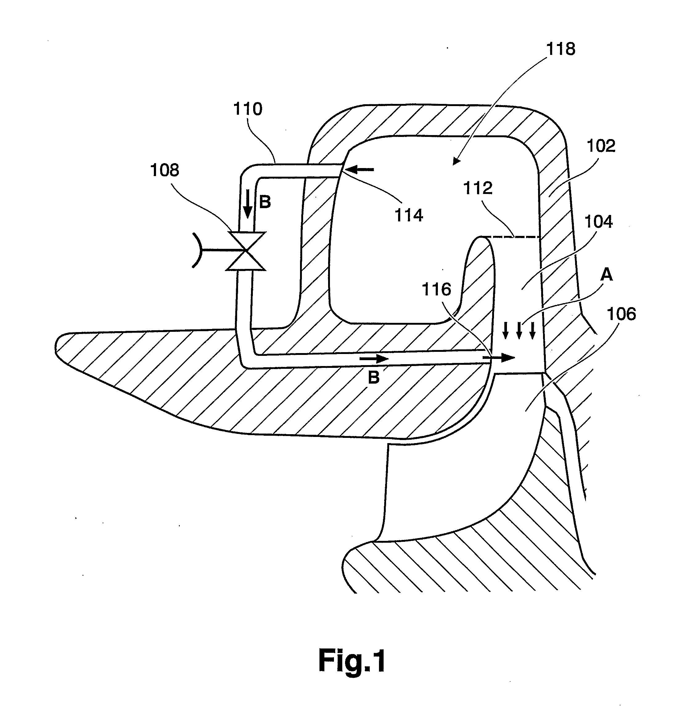
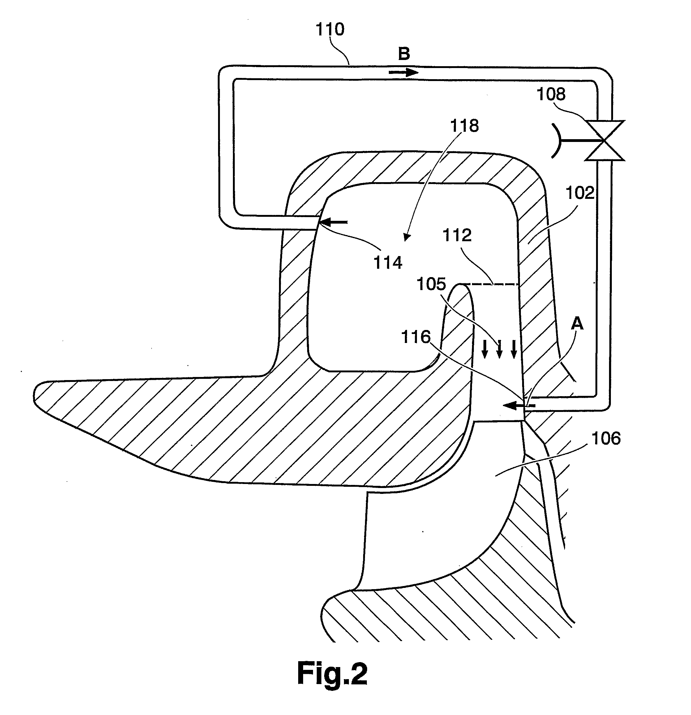
[0036]FIG. 1-5 depicts cross sections of a part of a turbo unit according to different example embodiments of the present invention. FIG. 1 depicts a volute housing 102, a vane 104, a turbine rotor 106, valve 108, pipe 110, gas flow inlet 114, gas flow outlet 116, volute 118. The volute housing 102 is part of the complete turbo unit housing, which also inter alia comprises a bearing housing and a compressor housing, which are not illustrated in FIG. 1-5. The turbo unit housing is in the present context defined as any part which make up the complete turbo unit.

[0037]Exhaust gas from an internal combustion engine flows into the volute 118 in a direction indicated by arrows A in FIG. 1-5. When exhaust gas is passing the turbine 106 said turbine starts to rotate. The embodiment in FIG. 1 is also provided with adjustable vanes 104 for increasing or decreasing the flow of exhaust gas through the turbine. A flow of gas is provided by an outlet 116 which is arranged in a turbine scroll area...


PUM


Abstract

A method of controlling turbine efficiency in a turbo unit provided on an internal combustion engine includes providing a flow of gas in an area upstream a turbine at a direction different to the flow of exhaust gases in the same area, regulating the flow by a valve, and controlling the valve from a control unit having at least boost pressure and / or EGR flow as input parameters.

Description

BACKGROUND AND SUMMARY[0001]The present invention relates to a method and an apparatus for controlling turbine efficiency in a turbo unit provided on an internal combustion engine.[0002]Turbochargers are well known and widely used with combustion engines for purpose of increasing power output, decreasing fuel consumption and emissions, and compensating for air density loss at high altitudes. Generally, turbochargers supply an increased charge air supply for the combustion process than can otherwise be induced through natural aspiration by utilizing exhaust gas energy to drive an air compressor. This increased air supply allows more fuel to be burned, thereby increasing power and output not otherwise obtainable from an engine having a given cylinder displacement under natural aspiration conditions. Variable geometry turbochargers (VGTs) allow the intake airflow to be optimized over a range of engine speeds. This may be accomplished by changing the angle of the inlet guide vanes on th...

Claims


Application Information

Patent Timeline
IPC IPC(8): F02B37/12F02B37/24
CPCF02D41/0077F02M25/0707F02M25/0713F02B37/12F02M25/0704F02D23/00F02D41/0007Y02T10/144Y02T10/47F02B37/24F02M26/05F02M26/10F02M26/02Y02T10/12Y02T10/40
Inventor ANDERSSON, PERBAUER, MARTIN
Owner VOLVO LASTVAGNAR AB
Why Eureka
Try Eureka