Device and method for deblocking optical workpieces, in particular spectacle lenses

a technology for optical workpieces and block pieces, applied in the direction of optical surface grinding machines, applications, manufacturing tools, etc., can solve the problems of spectacle lens fracture, spectacle lens damage, and it is not possible to apply hydraulic forces to separate the spectacle lens from the block piece, so as to reduce the risk of damage to the workpiece during the deblocking process, promote the separation of workpiece and block piece, and accelerate the deblocking process

Active Publication Date: 2015-01-13
SATISLOH AG
View PDF11 Cites 11 Cited by
  • Summary
  • Abstract
  • Description
  • Claims
  • Application Information

AI Technical Summary

Benefits of technology

[0014]Due to the fact that the high-pressure jet of pressure medium by contrast with the prior art defining the category is no longer incident or incident less by chance on the separating point between block piece and blocking material or the separating point between blocking material and workpiece, but as a consequence of the relative (height) adjustability e.g. height of nozzle and block piece can be directed selectively onto the respective separating point with CNC technology it is possible to significantly more quickly deblock the workpiece, which predestines the device / method according to the invention particularly for use in RX workshops. In this regard, a rapid deblocking process can be beneficially operated with a relatively high pressure of the pressure medium without a risk of the workpiece being damaged by the high-pressure jet of pressure medium, because due to the capability of selective movement to the relative setting of nozzle and block piece or workpiece it is possible to avoid scanning of the workpiece in a critical manner by the high-pressure jet of pressure medium. Thus, workpieces blocked by, in particular, adhesives can be deblocked rapidly, safely and free of damage without needing advance soaking and / or softening procedures and / or temperature-controlled pressure medium for the deblocking.
[0025]In a further advantageous embodiment of the deblocking device the suction head aligned with the axis of rotation of the workpiece is movable by a piston-cylinder arrangement in the direction of the axis of rotation of the workpiece (linear movement Y′), so that in the above step (iv) it is ultimately possible to still apply to the workpiece, a predetermined pulling force, by the piston-cylinder arrangement via the suction head sucking the second optically effective surface during the deblocking. This force advantageously is only slightly smaller than the retaining force produced at the workpiece by the suction head, this similarly being beneficial for a rapid deblocking process.

Problems solved by technology

A disadvantage of the inside application of the hydraulic forces is to be seen in that the block piece is provided with cavities which are open towards the blocking surface and which stand in the way of a desirable whole-area support of the spectacle lens at the block piece.
In principle, the opening in the blocking surface can indeed be reduced in order to achieve an approximately whole-area support, but then it is barely possible to apply the hydraulic forces in order to separate the spectacle lens from the block piece.
However, during the deblocking, mechanical forces are then applied by way of this piston to a relatively small central area at the spectacle lens, which can have the consequence of destroying the spectacle lens.
Particularly in the case of thin spectacle lens this can have the consequence of comparatively strong deformations and high levels of stress in the spectacle lens to be deblocked, which ultimately can produce fracture of the spectacle lens, quite apart from the outlay involved in providing such a piston in the block piece.
A disadvantage of this prior art is to be seen particularly in that—also a consequence of the intermediate preheating step in the hot water bath—the deblocking of a spectacle lens takes a relatively long time, which represents an obstacle to efficient use of this method in RX workshops.

Method used


Image

  • Device and method for deblocking optical workpieces, in particular spectacle lenses
  • Device and method for deblocking optical workpieces, in particular spectacle lenses
  • Device and method for deblocking optical workpieces, in particular spectacle lenses

Examples


first embodiment

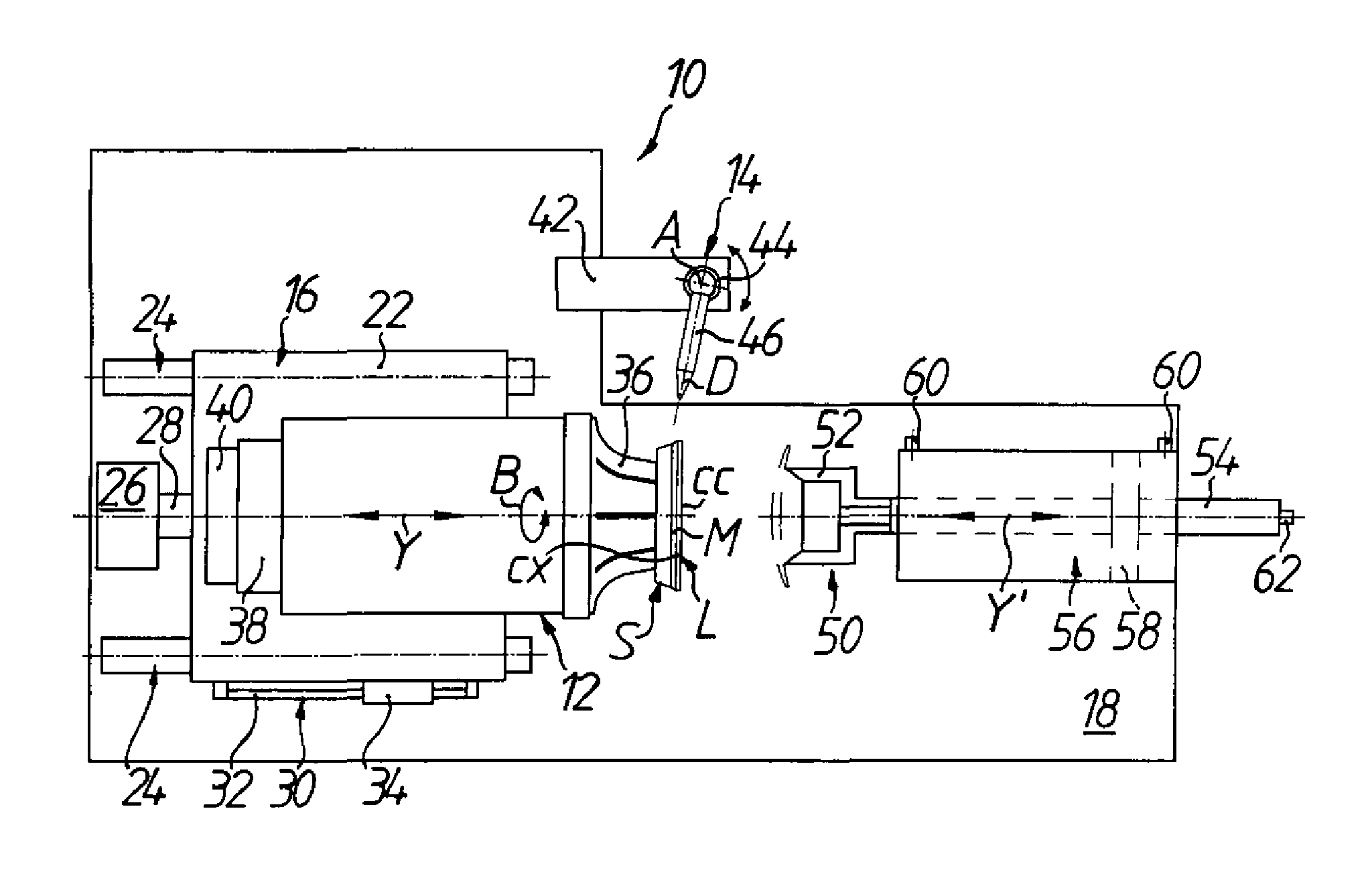
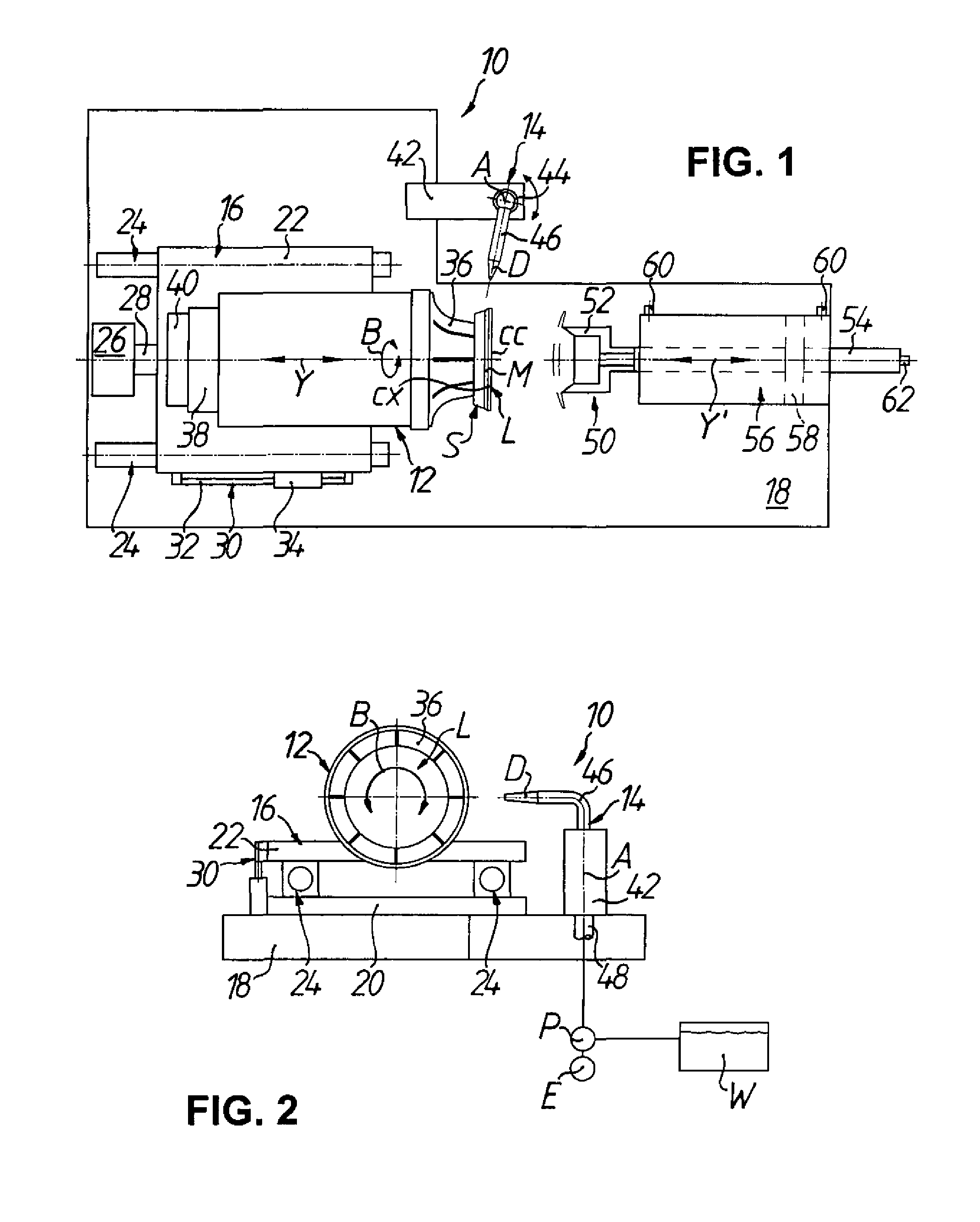
[0032]In the first embodiment according to FIGS. 1 and 2 a device for deblocking spectacle lenses L as optical workpieces is denoted by 10. The deblocking device 10 comprises, in general terms, a first movement device 12 for rotating the spectacle lens L, which is blocked on a block piece S, about an axis B of workpiece rotation, a nozzle subassembly 14 with a nozzle D for delivery of a high-pressure water jet, for example, a pressure-medium high-pressure jet HDS illustrated in FIG. 5, in a direction substantially transverse to the axis B of workpiece rotation onto an edge region between spectacle lens L and block piece S, and a second movement device 16 for generating a relative movement between the spectacle lens L and the nozzle D along the axis B of workpiece rotation. It is significant that the spectacle lens L is displaceable with respect to the nozzle D—or, as an alternative (not illustrated) thereto, conversely the nozzle with respect to the spectacle lens—by the second move...

second embodiment

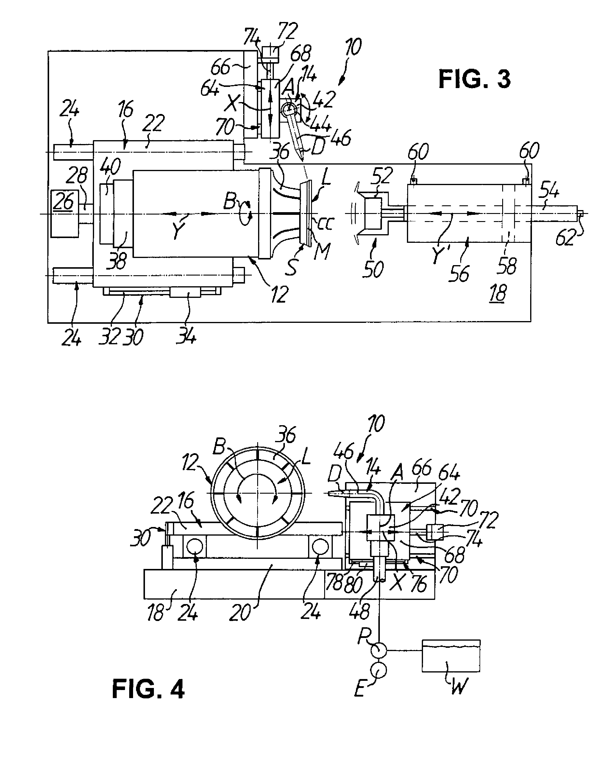
[0039]The significant difference consists here in that in the case of the second embodiment illustrated in FIGS. 3 and 4 has the deblocking device 10 provided with a third movement device 64 for producing a positionally regulated (X-axis) relative movement between the spectacle lens L and the nozzle D in a direction substantially perpendicular to the axis B of workpiece rotation, which serves the purpose of setting in defined manner a clear spacing ad (see, again, FIG. 5) between the nozzle D—more specifically the outlet thereof—and the predetermined place MAP of incidence of the high-pressure water jet HDS.

[0040]In addition, the third movement device 64 has a bracket 66 which is attached to the base plate 18. An X-carriage 68 (nozzle carriage) of the third movement device 64 is mounted on the bracket 66 by way of two linear guides 70, which are arranged in parallel and spaced from one another in height direction in FIG. 4, to be longitudinally displaceable. Each linear guide 70 has...


PUM

PropertyMeasurementUnit
setting angleaaaaaaaaaa
pressureaaaaaaaaaa

Abstract

The invention relates to a deblocking device and an associated method for deblocking optical workpieces, for example, eyeglass lenses. The deblocking device has a first moving apparatus for rotating a workpiece blocked on a block piece about a workpiece rotational axis, a nozzle assembly having a nozzle for discharging a high-pressure pressure medium jet in a direction substantially perpendicular to the workpiece rotational axis onto an edge area between the workpiece and block piece, and a second moving apparatus for generating a relative motion between the workpiece and the nozzle along the workpiece rotational axis.

Description

TECHNICAL FIELD[0001]The present invention relates generally to a device for deblocking optical workpieces, for example, spectacle lenses, as well as to such a method.BACKGROUND OF THE DISCLOSURE[0002]In the manufacture of optical products “block mounting” or, for short, “blocking” generally denotes the process in which an optical workpiece is temporarily fastened on a so-called “block piece” by a suitable material (low-melting-point alloy or adhesive) or, however, the blocking material is mounted on the workpiece in order itself to form the block piece, which then serves the purpose of holding the workpiece in the respective processing machine and / or coating installation. Correspondingly, in manufacture of optical products “deblocking” defines that process in which the optical workpiece after processing and / or coating thereof is again separated from the block piece or blocking material.[0003]The invention relates particularly to a device and a method for deblocking spectacle lenses...

Claims


Application Information

Patent Timeline
Patent Type & Authority Patents(United States)
IPC IPC(8): B23Q3/00B24B13/005
CPCB24B13/0057B29D11/00432B29D11/00942Y10T29/49815
Inventor PAVEL, GREGORKRAFT, THORSTENSCHAFER, HOLGER
Owner SATISLOH AG
Why Eureka
Try Eureka