Medical transceiver device and method

a transceiver and medical technology, applied in diversity/multi-antenna systems, antenna supports/mountings, polarisation/directional diversity, etc., can solve the problems of patents providing no solution for determining the optimum polarization, and the reception antenna will only sense maximum signal strength, etc., to achieve efficient use of available space, easy to tune, and mechanically durable

Active Publication Date: 2015-01-20
ST JUDE MEDICAL
View PDF7 Cites 2 Cited by
  • Summary
  • Abstract
  • Description
  • Claims
  • Application Information

AI Technical Summary

Benefits of technology

[0015]A yet further object of the invention is to provide such a medical transceiver device, which is possible to manufacture to a rather low cost, is easy to tune, and enables an efficient use of available space.
[0016]A still further object of the invention is to provide such a medical transceiver device, which is reliable, and particularly mechanically durable.

Problems solved by technology

Another problem when transferring signals between two antennas is, however, that the receiving antenna will only sense maximum signal strength if its polarization state is similar to the polarization state of the incoming signal.
A particular problem when transferring radio-based signals between an implantable medical device and an external device is due to the fact that the antenna polarization of the implantable medical device will be arbitrary.
The patents provide no solution for determining an optimum polarization state for radio frequency signals to be transmitted to the implantable medical device and / or to be received from there.

Method used


Image

  • Medical transceiver device and method
  • Medical transceiver device and method
  • Medical transceiver device and method

Examples


Embodiment Construction

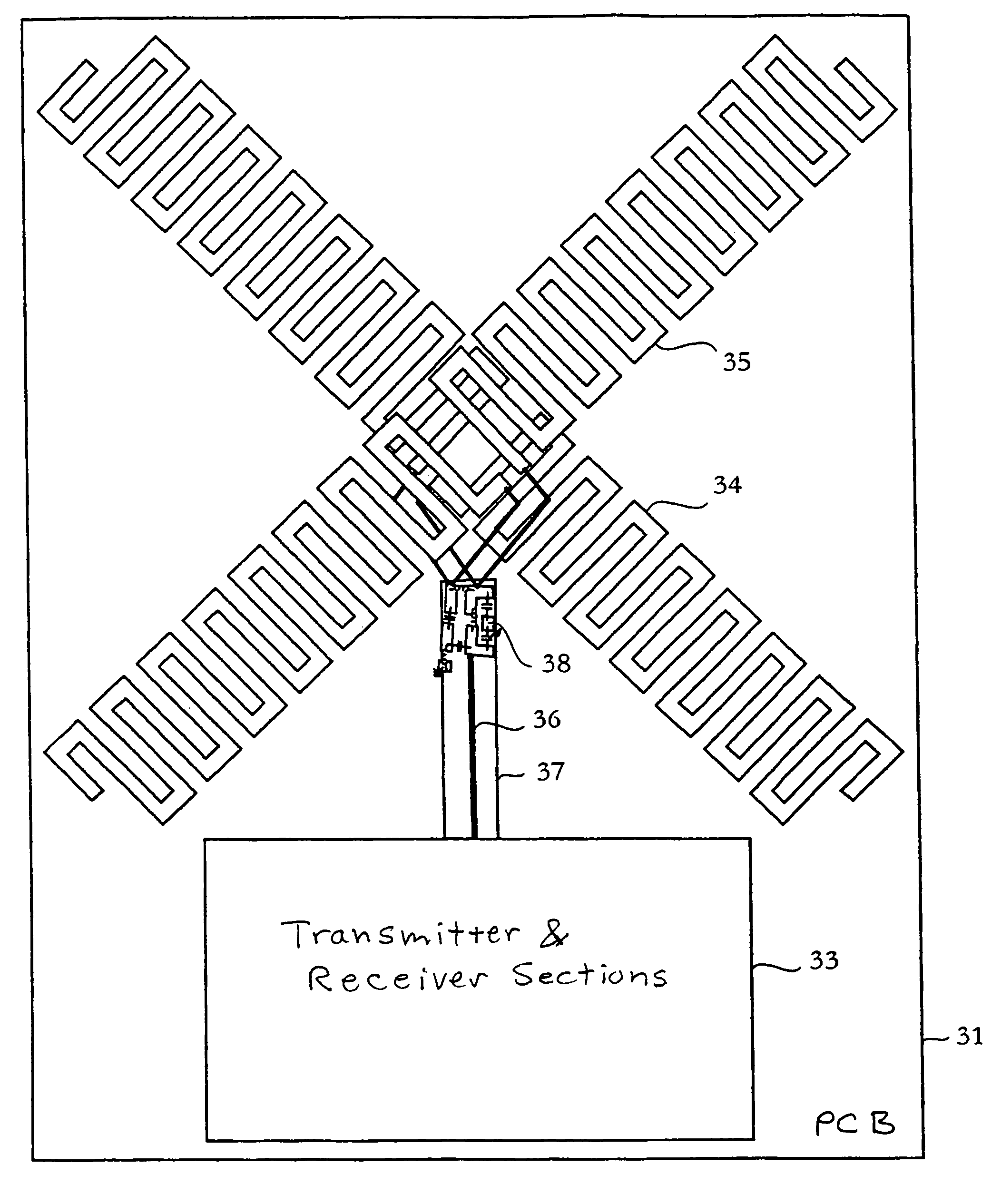
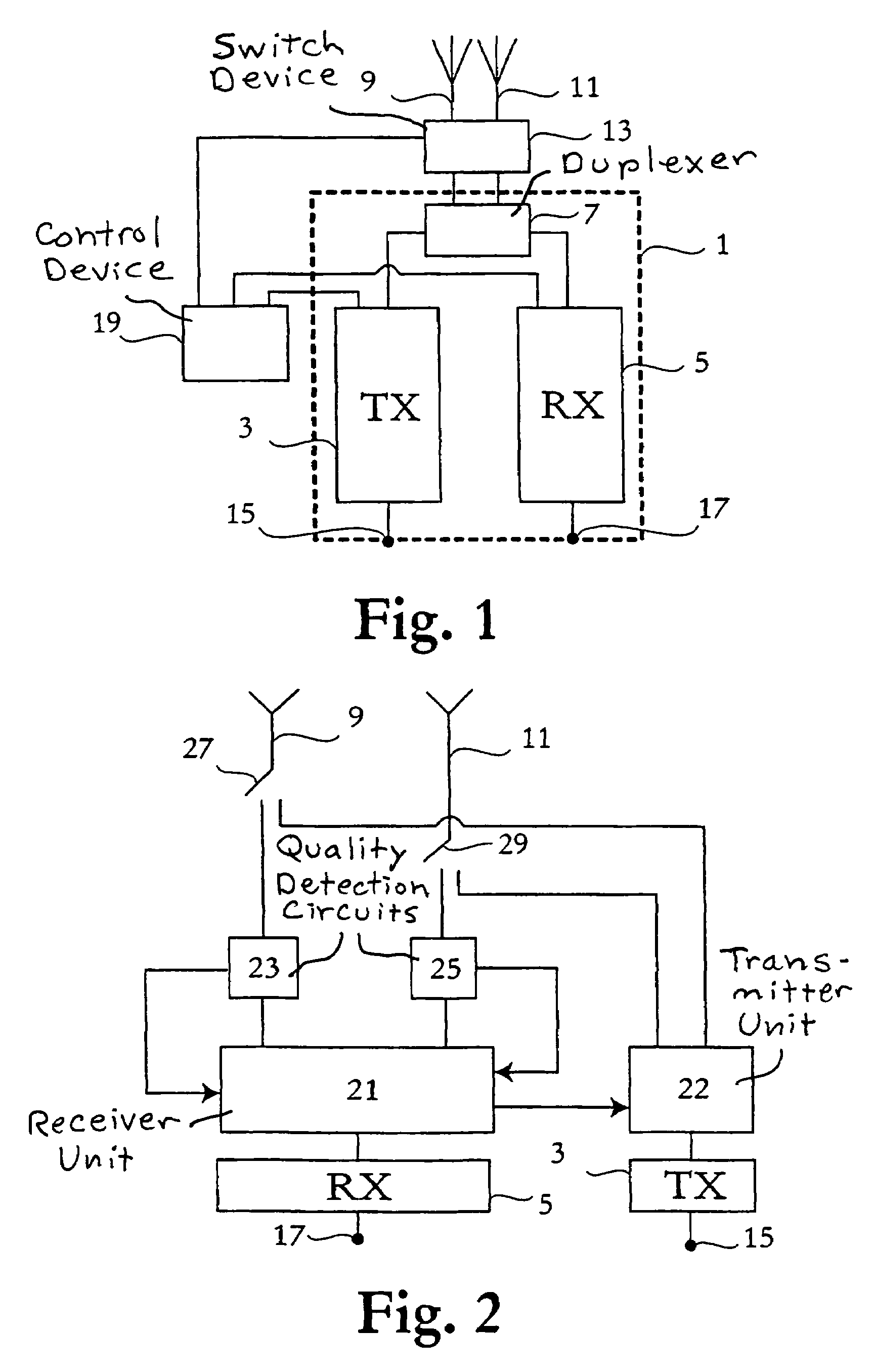
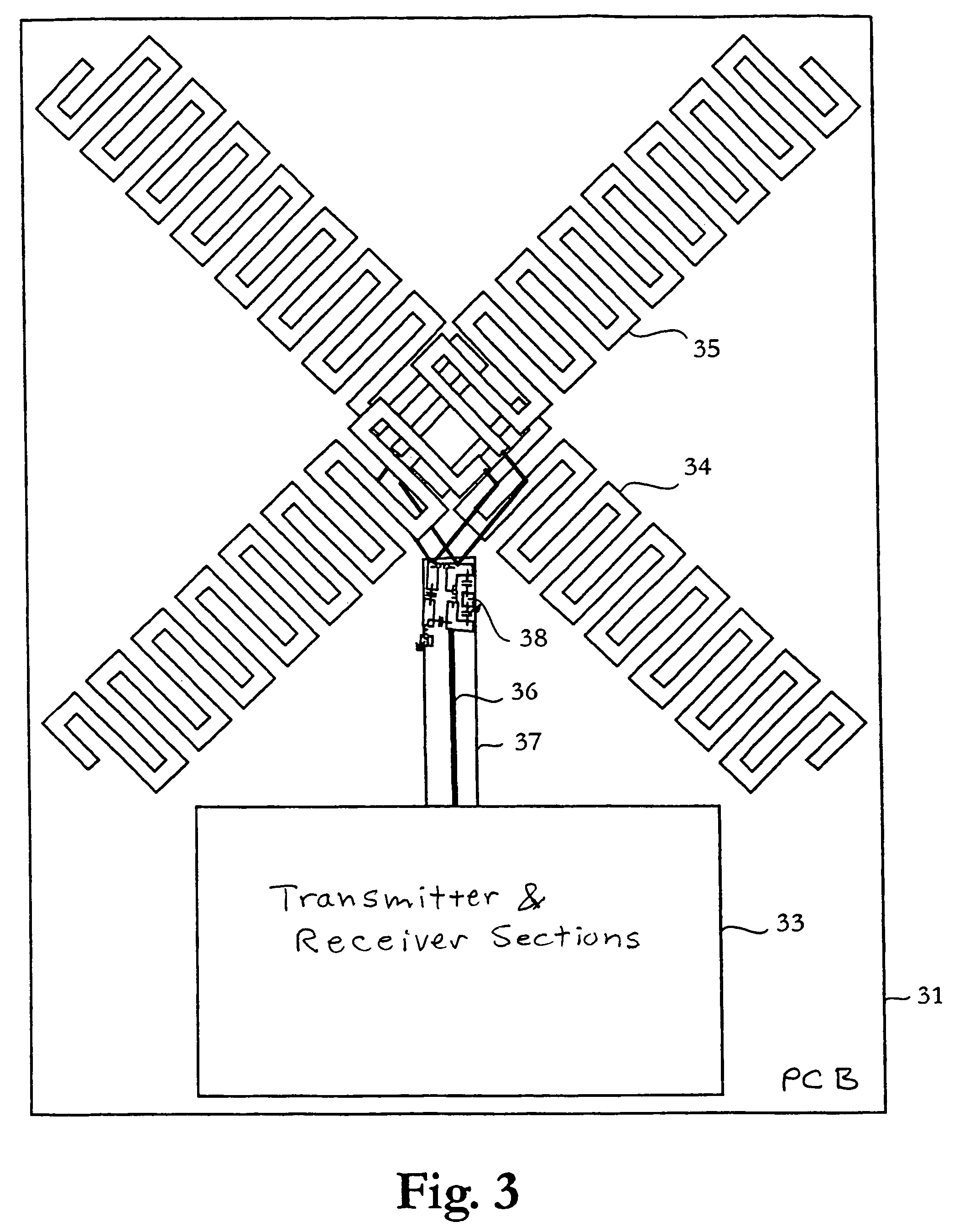
[0028]With reference to FIG. 1, a medical transceiver device for radio-based communication with an implantable medical device according to a preferred embodiment of the present invention comprises circuitry 1 connected to first and second electrically conductive and radiating structures or antennas 9, 11 via a switch device 13. A control device 19 is connected to the circuitry 1 and to the switch device 13.

[0029]The circuitry 1, which comprises transmitter 3 and receiver 5 sections connected to the switch device 13 and electrically conductive structures 9, 11 via a duplexer 7, is a high frequency part of the medical transceiver device provided for transmitting radio frequency signals to, and receive radio frequency signals from, an implantable medical device (not illustrated) via the first and second radiating structures 9, 11.

[0030]Thus, the circuitry 1 is preferably arranged to be electrically connected, via radio communications circuitry, to a digital or analog signal processor o...


PUM


Abstract

A medical transceiver device for radio-based communication with an implantable medical device has circuitry for transmitting radio-frequency signals to, and / or receiving radio-frequency signals from, the implantable medical device, first and second electrically conductive structures, and an antenna feed network operatively interconnected between the circuitry and the first and second conductive structures. Each of the first and second conductive structures is operable as a transmitting and / or receiving antenna for the radio-frequency signals. The first and second conductive structures emit and / or receive radio waves of different polarizations, and the first and second conductive structures are disposed adjacent each other at a single location in space, thereby providing spatial diversity that is independent of the polarization diversity.

Description

BACKGROUND OF THE INVENTION[0001]1. Field of the Invention[0002]The present invention relates to a medical transceiver device and a method, respectively, for radio-based communication with an implantable medical device, and to a system comprising the medical transceiver device and the implantable medical device.[0003]2. Description of the Prior Art[0004]In the context of implantable medical devices, it has become common to provide a communication link between the implanted device and an external programmer or monitor in order to allow for transmission of commands from the external device to the implanted device and to allow for transmission of stored information and / or sensed physiological parameters from the implanted device to the external programmer. Conventionally, communication between an implanted device and an external programmer has been accomplished by means of a telemetry system, which includes a transceiver located within the implanted medical device and an external progr...

Claims


Application Information

Patent Timeline
Patent Type & Authority Patents(United States)
IPC IPC(8): H01Q1/22A61N1/372H04B7/10
CPCA61N1/37229A61N1/37223H04B7/10H01Q1/22
Inventor ABRAHAMSON, HANSSNITTING, TOMAS
Owner ST JUDE MEDICAL
Why Eureka
Try Eureka