Process and apparatus for producing beam member

a beam member and process technology, applied in the direction of transportation and packaging, other domestic objects, bands, etc., can solve the problems of insufficient rigidity, insufficient junction strength, and insufficient rigidity of resin-rich gaps, so as to achieve continuous and efficient filling of gaps

Active Publication Date: 2015-01-27
TORAY IND INC
View PDF9 Cites 5 Cited by
  • Summary
  • Abstract
  • Description
  • Claims
  • Application Information

AI Technical Summary

Benefits of technology

[0013]In the light of the above problems, in producing the beam member made of the reinforcing fiber base material, the present invention provides a process and an apparatus for producing a beam member where a shaped filler to be filled in the gap is capable of being continuously and efficiently produced even in the case where a cross-sectional surface of the gap having a wedge shape formed at a branching point of a reinforcing fiber base materials changes in a longitudinal direction of the beam member, at a cross-sectional surface orthogonal to the longitudinal direction of the beam member.
[0037]The “reinforcing fiber base material which has a web portion and at least a set of flange portions extending to both sides via at least one branching point from the web portion” is a combined object that constitutes a web portion and a flange portion by combining at least plural reinforcing fiber base materials having bent portions. For example, as shown in FIG. 1, a web portion and a flange portion can be formed by combining three reinforcing fiber base materials 10a to 10c. Alternatively, a web portion and a flange portion can be formed by only plural reinforcing fiber base materials having bent portions, without the reinforcing fiber base material 10c on a flat plate as shown in FIG. 1. The “flange portion” is a horizontal plate element provided at an upper edge (or a lower edge) in a beam member of a T-shaped cross-sectional surface, for example. The “web” portion is a perpendicular plate element connected to the flange portion. Mainly by applying a resistance force acting on a bending moment of the flange portion and a resistance force acting on the shearing force of the web portion, a cross-sectional secondary moment becomes large, and bending rigidity improves.
[0041]According to embodiments of the process and the apparatus for production in the present invention, as explained below, in producing a beam member made of reinforcing fiber base materials, even when a cross-sectional surface shape of a wedge gap (a gap portion that is formed at a portion where a pair of reinforcing fiber base materials branches, for example) on a cross-sectional surface which is orthogonal to a longitudinal direction of the reinforcing fiber base material changes in the longitudinal direction of the reinforcing fiber base material, a shaped filler to fill the gap is continuously and efficiently produced, and a high-definition beam member can be obtained.

Problems solved by technology

The gap occurs because the reinforcing fiber base materials cannot be completely deformed at a right angle due to high rigidity of the fibers when the reinforcing fiber base materials are bent.
When this molded article is applied to a wing or the like of an aircraft, the resin-rich gap generates insufficient rigidity and insufficient junction strength when a large tensile load acts, and this has a possibility of becoming a start point of break.
Because fibers of the branching point are disturbed by a resin injection pressure at a molding time and because a gap ratio of the preform locally varies, there is a risk of occurrence of a void which becomes an internal defect of the molded article in the resin-rich gap.
In this case, a problem occurs because a cross-sectional surface of the gap changes continuously or at stages following a change of the thickness of the beam member.
This is because the cross-sectional surface area of a shaped filler that fills the wedge gap is difficult to be changed along a longitudinal direction.
When a shaped filler having a constant cross-sectional surface area is used, many gaps remain in some places, or conversely, a density of reinforcing fibers contained in the cross-sectional surface of the gap becomes excessive.
As a result, strength reduction or delamination occurs easily.
Therefore, facility cost to produce the shaped filler increases, and a work process becomes extremely complex.
Because dies need to be prepared or exchanged each time, it takes time and labor, resulting in inefficiency.

Method used


Image

  • Process and apparatus for producing beam member
  • Process and apparatus for producing beam member
  • Process and apparatus for producing beam member

Examples


Embodiment Construction

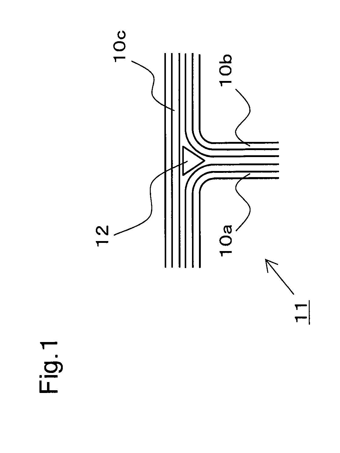
[0056]A preferred embodiment of a process and an apparatus for producing a beam member according to the present invention is explained below with reference to the drawings. Specifically, there is explained a case of changing an R shape (a curvature radius) of a curve line forming a wedge shape of a shaped filler, from a large R shape to a small R shape, corresponding to a change of a cross-sectional shape of a gap formed at a branching point of reinforcing fiber base materials that makes a pair configuring a beam member.

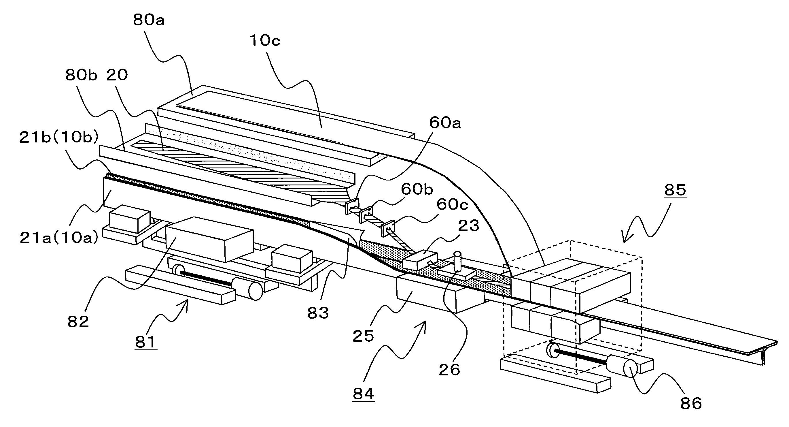
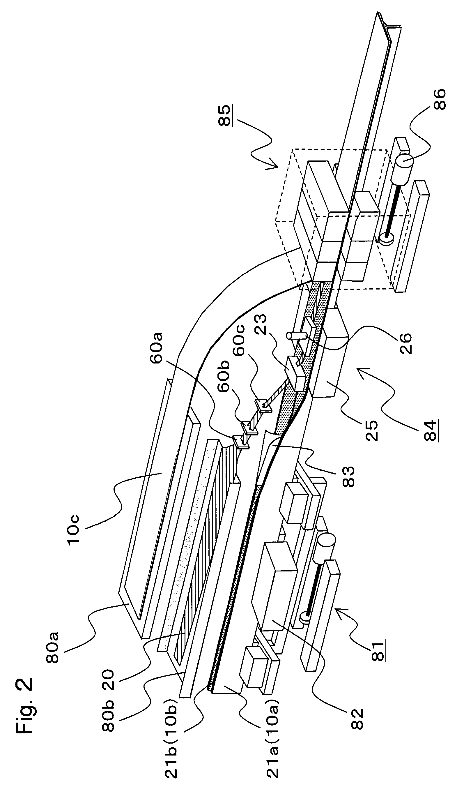
[0057]FIG. 2 is a schematic perspective view showing an example of an apparatus for producing a beam member according to the present invention. More specifically, FIG. 2 shows an apparatus that produces a beam member with a T cross-sectional shape shown in FIG. 1. The apparatus mainly includes a material supplying apparatus (e.g. material supplying apparatuses 80a, 80b), a material carrying apparatus (e.g. a pulling apparatus 81), a web portion forming apparatus 82, ...


PUM

PropertyMeasurementUnit
glass transition temperatureaaaaaaaaaa
softening temperature Tgaaaaaaaaaa

Abstract

A process for producing a beam member formed by a reinforcing fiber base material which has a web portion and at least a pair of flange portions extending to both sides via at least a branching point from the web portion, at a cross-sectional surface orthogonal to a longitudinal direction of the beam member, and by a shaped filler which fills a gap having a wedge shape formed at the branching point, is provided. The shaped filler is produced by: (A) a filler supply process for supplying a filler member configured by reinforcing fibers; (B) a preshaping process for providing a preshaped filler having at least a wedge projection portion, by pressurizing the filler member by a preshaping mold; and (C) a filler deforming process for providing a shaped filler by deforming the preshaped filler.

Description

CROSS REFERENCE TO RELATED APPLICATIONS[0001]This application is the U.S. National Phase application of PCT International Application No. PCT / JP2010 / 067942, filed Oct. 13, 2010, and claims priority to Japanese Patent Application No. 2009-238825, filed Oct. 16, 2009, the disclosure of which is incorporated herein by reference in its entirety for all purposes.FIELD OF THE INVENTION[0002]The present invention relates to a process and an apparatus for producing a beam member made of a reinforcing fiber base material. More particularly, the invention relates to a process and an apparatus for efficiently producing a shaped filler made of a fiber structure which is to fill as a reinforcing member a wedge gap of a beam member in a cross-sectional surface orthogonal to a longitudinal direction.BACKGROUND OF THE INVENTION[0003]Carbon-fiber reinforced plastics (CRFP) and glass-fiber reinforced plastics (GFRP) that use carbon fibers, glass fibers, or aramid fibers as reinforcing fibers have lig...

Claims


Application Information

Patent Timeline
Patent Type & Authority Patents(United States)
IPC IPC(8): B32B3/04B32B38/08B32B37/12B29B11/16B29C70/50B29C70/86B29L31/00
CPCB29C70/50B29C70/865B29B11/16B29L2031/008B29D99/0007Y10T428/24264Y10T156/1051B29D99/0005
Inventor HANAWA, TATSUYASUZUKI, TAMOTSU
Owner TORAY IND INC
Why Eureka
Try Eureka