Multi-cylinder internal combustion engine and method for operating a multi-cylinder internal combustion engine

a multi-cylinder, internal combustion engine technology, applied in the direction of machines/engines, electric control, ignition automatic control, etc., can solve the problems of increased charge cycle losses, engine efficiency and thus fuel economy compromise, and is not suitable for retrofitting to engines already on the market, so as to reduce the charge cycle loss

Active Publication Date: 2015-02-03
FORD GLOBAL TECH LLC
View PDF6 Cites 22 Cited by
  • Summary
  • Abstract
  • Description
  • Claims
  • Application Information

AI Technical Summary

Benefits of technology

[0045]Additionally, the direct injection of the fuel into the cylinders, like the partial cutoff itself, provides some dethrottling of the internal combustion engine, so that the two measures, the partial cutoff on the one hand and the direct injection on the other, enhance one another in the dethrottling.

Problems solved by technology

However, in the partial load range, since small loads require a high degree of throttling and pressure reduction in the intake tract, charge cycle losses increase as the load diminishes and the throttling increases.
As a result, engine efficiency and thus fuel economy are compromised.
The concepts described above have the disadvantage that they are not suitable for retrofitting to engines already on the market, since they require substantial modifications to the basic engine and / or the valve gear, and additional complex components.
Besides the aforementioned advantages, partial cutoff, particularly in multi-cylinder internal combustion engines having an odd number n of cylinders, also have disadvantages, which are often an obstacle to use in series production.
In the context of a partial cutoff, the cutoff cylinder is deactivated and only the two remaining cylinders continue to operate, so that an irregular firing pattern ensues, in which the firing interval alternates between 240° CA and 480° CA, which results in several detrimental effects.
The irregular firing pattern leads to an unharmonious engine noise, which is perceived as unpleasant.
This is disadvantageous, since the noise generated by the internal combustion engine has a considerable influence on customers' purchasing behavior.
Further, excitation of the crankshaft in the natural frequency range can result in high rotational oscillation amplitudes, which can even lead to fatigue fracture.

Method used


Image

  • Multi-cylinder internal combustion engine and method for operating a multi-cylinder internal combustion engine
  • Multi-cylinder internal combustion engine and method for operating a multi-cylinder internal combustion engine
  • Multi-cylinder internal combustion engine and method for operating a multi-cylinder internal combustion engine

Examples


Embodiment Construction

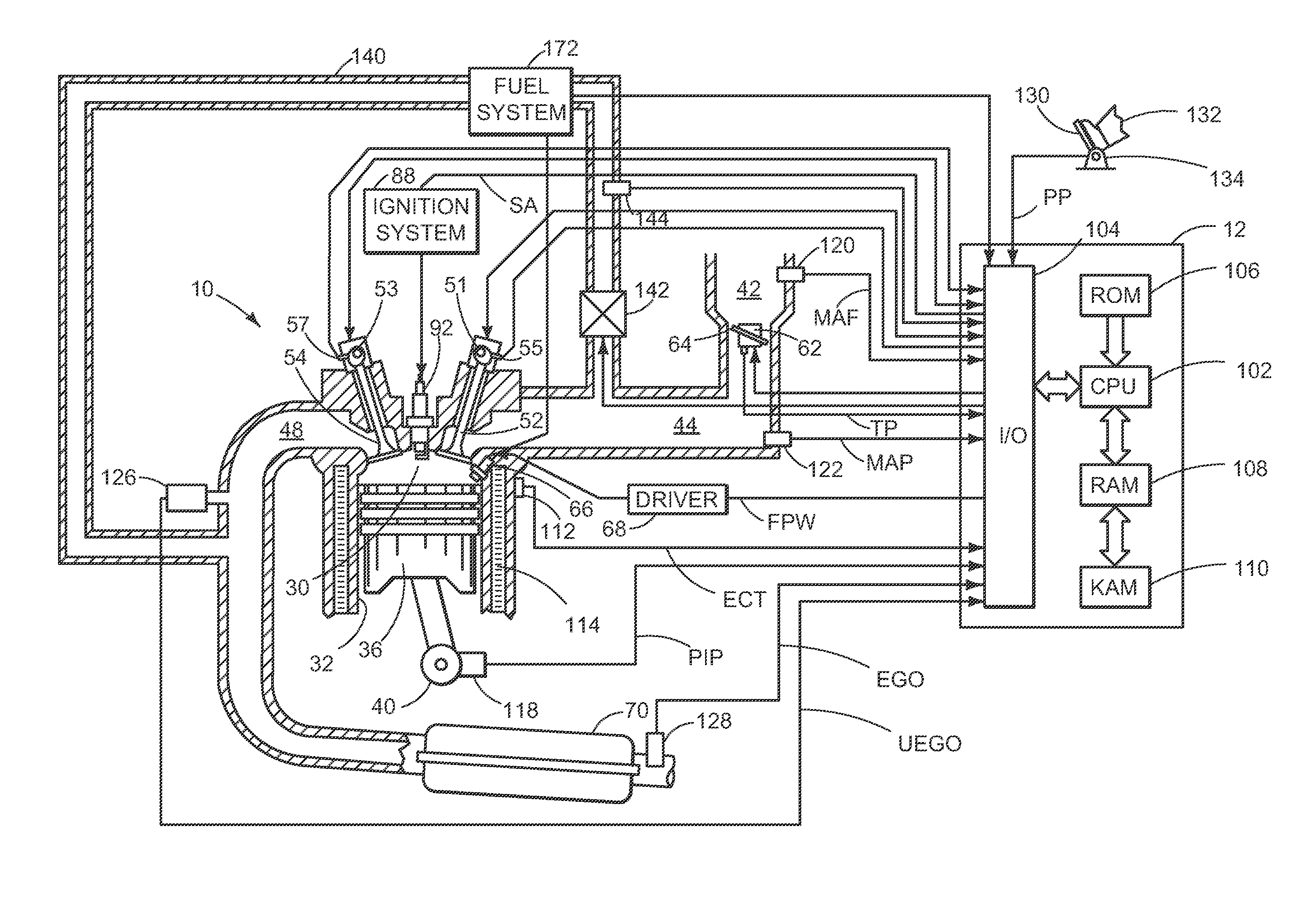
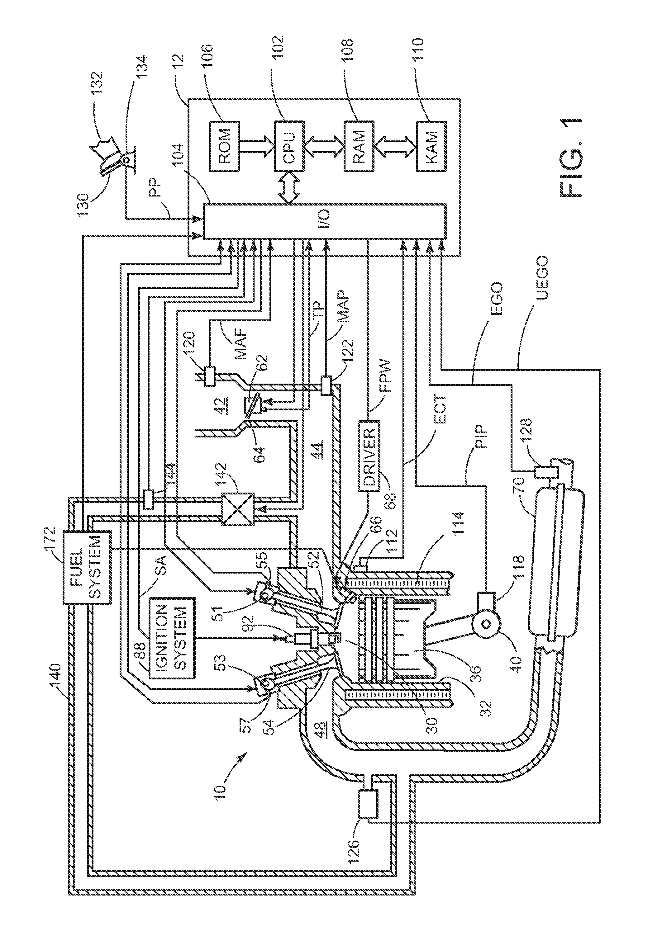
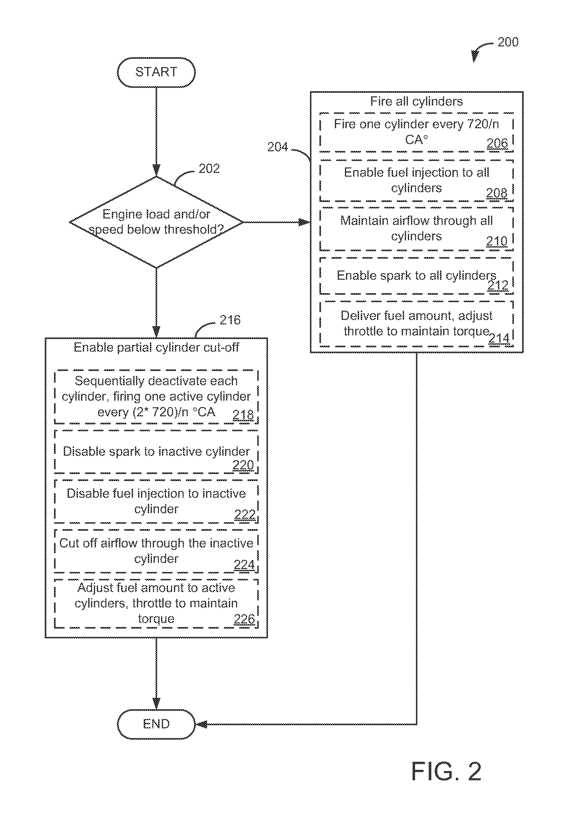
[0023]In order to dethrottle the engine to improve fuel economy, a partial cylinder cutoff may be activated in which each cylinder is cut off in turn. FIG. 1 shows an example engine that can be operated in the partial cutoff mode according the method of FIG. 2. FIGS. 3-6 depict ignition timing diagrams during the execution of the method of FIG. 2.

[0024]Referring now to FIG. 1, a schematic diagram showing one cylinder of multi-cylinder engine 10, which may be included in a propulsion system of an automobile, is illustrated. Engine 10 may be controlled at least partially by a control system including controller 12 and by input from a vehicle operator 132 via an input device 130. In this example, input device 130 includes an accelerator pedal and a pedal position sensor 134 for generating a proportional pedal position signal PP. Combustion chamber (i.e., cylinder) 30 of engine 10 may include combustion chamber walls 32 with piston 36 positioned therein. Piston 36 may be coupled to cran...


PUM


Abstract

A method for partial cylinder cutoff is provided. The method comprises operating a multi-cylinder internal combustion engine with applied ignition, in which an odd number n of cylinders is arranged in line, and during partial-load operation when engine load is below threshold, enabling a partial cutoff of the cylinders, the partial cutoff comprising operating each cylinder only intermittently such that each cylinder is fired and cut off in turn at an interval of (2*720° CA) / n.

Description

RELATED APPLICATIONS[0001]This application claims priority to German Patent Application No. 102010037362.1, filed on Sep. 7, 2010, the entire contents of which are being incorporated herein by reference.FIELD[0002]The disclosure relates to a multi-cylinder internal combustion engine with applied ignition.BACKGROUND AND SUMMARY[0003]Spark-ignition engines operate with a homogeneous fuel-air mixture which, in the absence of direct injection, is prepared through external mixture formation by introducing fuel into the intake air in the intake tract. The required power output is adjusted by varying the combustion chamber charge so that, unlike in the diesel engine, operation of the spark-ignition engine is based on a quantitative control.[0004]The load is generally controlled by means of a throttle valve provided in the intake tract. By adjusting the throttle valve the pressure of the intake air downstream of the throttle valve can be reduced to a greater or lesser degree. The further th...

Claims


Application Information

Patent Timeline
Patent Type & Authority Patents(United States)
IPC IPC(8): F02D13/06F02B3/00F02D45/00F02D17/00F02P5/14F02D13/02F02D17/02F02D41/00F02M25/07
CPCF02D41/0087F02D13/06F02D17/02F02D13/0207F02D13/0219F02M25/0754F02M25/0755Y02T10/18F02B75/20F02B2075/182F02M26/46F02M26/47Y02T10/12F02D41/0002F02P9/00
Inventor TOBERGTE, MICHAELWEBER, CARSTENHOHENBOEKEN, KAYRUHLAND, HELMUT HANSPINGEN, BERT
Owner FORD GLOBAL TECH LLC
Why Eureka
Try Eureka