Surgical manipulation instrument

a technology of manipulating instruments and surgical instruments, applied in the field of surgical manipulation instruments, can solve the problems of reducing the space requirements of structural space, limiting the freedom of movement of surgical instruments, and affecting the accuracy of the monitor image, so as to achieve the effect of reducing the space requirements

Active Publication Date: 2015-02-03
DEUTSCHES ZENTRUM FUER LUFT & RAUMFAHRT EV
View PDF7 Cites 334 Cited by
  • Summary
  • Abstract
  • Description
  • Claims
  • Application Information

AI Technical Summary

Benefits of technology

[0015]Preferably, the first coupling element is of rotationally symmetric design, where it is particularly preferred that the undercut recess is annular. In a preferred embodiment, the coupling arms are correspondingly arranged on a circular ring, with the coupling arms embracing the first coupling element when the coupling device is in the closed state. The preferred design of the first coupling element as a rotationally symmetric coupling element offers the particular advantage that the parts to be coupled can be connected in a simple manner, since no orientation of the parts with respect to each other is required.
[0016]Furthermore, it is preferred that the first coupling element is rigid and thus has a great strength. In particular it is a solid body. This allows for a small structural size.
[0018]The first and / or the second coupling element are preferably firmly connected with the corresponding fastening element or may also be formed integrally with the same. Thereby, space requirements are reduced.
[0019]Preferably, the coupling elements of the coupling device are fixed or held exclusively by a clamping from outside. Thereby, the structural space can be reduced further.
[0020]In a particularly preferred embodiment, a fixing element is provided in addition. The fixing element serves to retain the coupling elements in the closed position. The fixing element thus helps to avoid an unintentional opening of the coupling device. If the second coupling element has coupling arms that are pivoted outward to be opened or closed, a fixing element may be provided that surrounds the coupling arms in the closed position and thereby prevents an outward directed pivoting of the coupling arms. Preferably, a slidable sleeve is provided as the fixing element. When the coupling device is closed, the sleeve surrounds the two coupling elements at least partly. It is advantageous, in particular when coupling arms are provided, to provide an annular sleeve that surrounds the coupling arms at least in the region of the radially extending projections. Opening the coupling device then merely requires shifting the sleeve so that the two coupling elements can be pulled apart again, where, if the second coupling element has coupling arms, these can be pivoted again. Preferably, the fixing element is spring-loaded, with the spring load being such that the fixing element has to be shifted against the spring force from the closed position to the open position. This guarantees that the operating staff cannot forget to arrange the fixing element in the closed position.
[0021]In a further preferred embodiment of the disclosure the second coupling element comprises radially displaceable holding elements such as balls or the like. By shifting the holding elements radially into the undercut recess, the coupling device is closed. A fixing element, which is preferably provided, helps to avoid that the holding elements move out from the undercut recess by themselves. This may be effected, for example, by making the individual holding elements spring-loaded on the direction of undercut recess. It is also possible to configure the fixing element such that it comprises a recess into which the balls can be shifted in order to release the coupling device, and to arrange the fixing element such that, in order to close the coupling device, the recess is offset towards the holding elements. In this case, the fixing element may again be designed to be displaceable.

Problems solved by technology

The disadvantages of minimally invasive surgery include, among others, the limited freedom of movement of the surgical instruments.
Since the passage opening in the epidermis and the fat tissue can be seen as being a stationary opening forming an invariable point, this results in inverted movement ratios or an impeded hand-eye coordination with respect to the monitor image.
This may possibly be achieved by manual operation, however, this requires great aptness and long practice.
However, the actuators for driving the surgical manipulation instrument can generally not be autoclaved.
However, this play has adverse effects in the operation of the manipulation instrument or may even make an automatic control impossible.
Such a coupling device in connection with translation means for translating a linear movement into a rotary movement or a rotary movement into a linear movement is extremely intricate.
A corresponding coupling device would not only be expensive and elaborate, but would also be heavily fraught with losses.
This is inacceptable in particular with surgical instruments used in minimally invasive surgery, since the transmission of forces and moments must be performed with utmost precision and as little play as possible.

Method used


Image

  • Surgical manipulation instrument
  • Surgical manipulation instrument
  • Surgical manipulation instrument

Examples


Embodiment Construction

with reference to preferred embodiments and to the accompanying drawings.

BRIEF DESCRIPTION OF THE DRAWINGS

[0027]In the Figures:

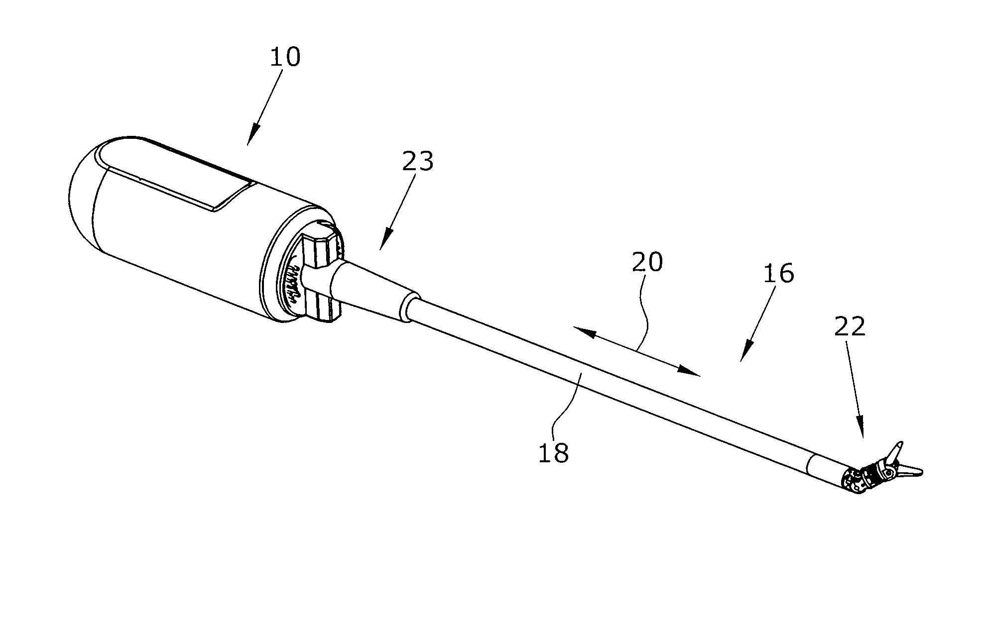
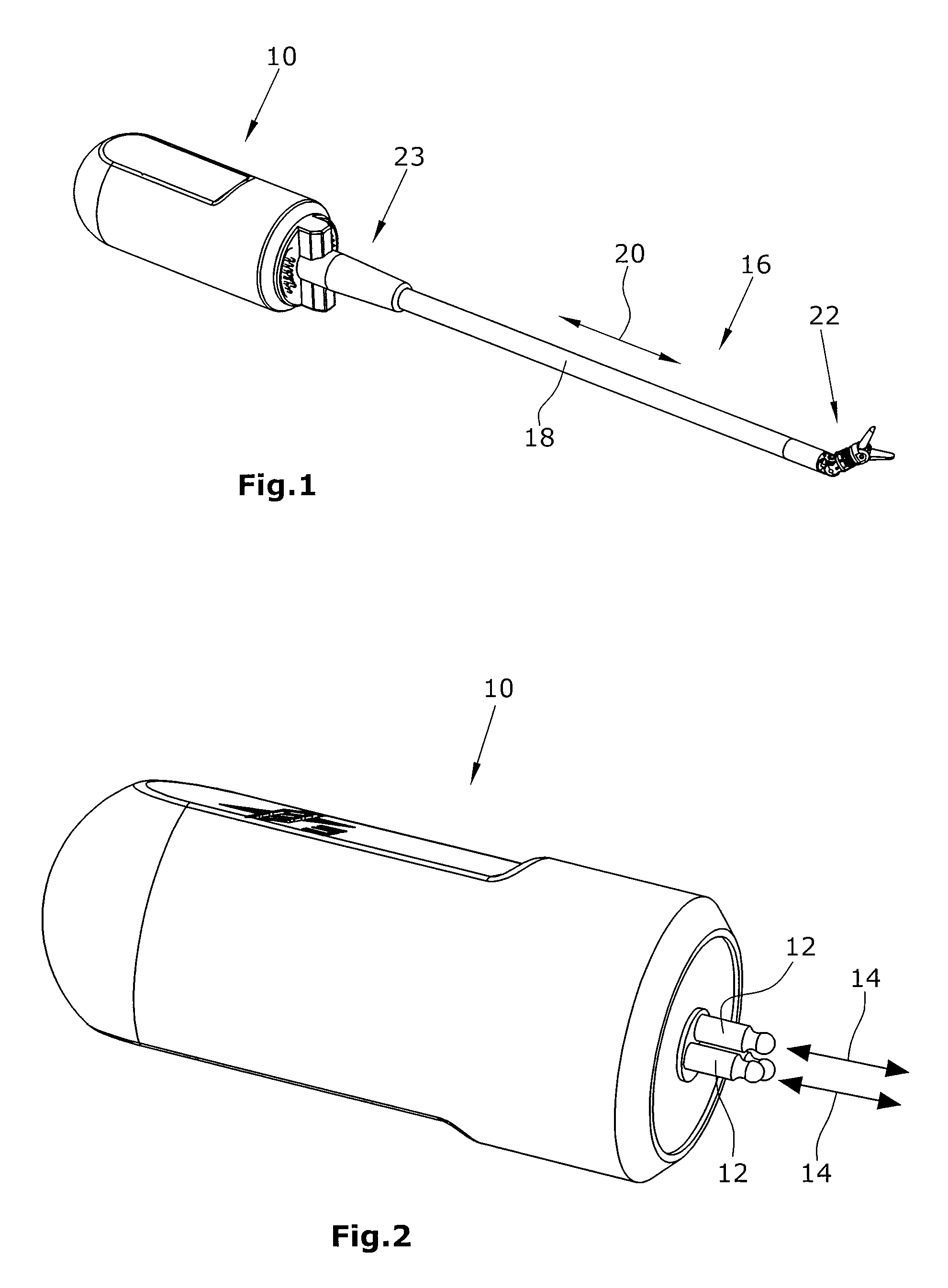
[0028]FIG. 1 is a schematic perspective view of a surgical manipulation instrument,

[0029]FIG. 2 is a schematic perspective side elevational view of the drive device,

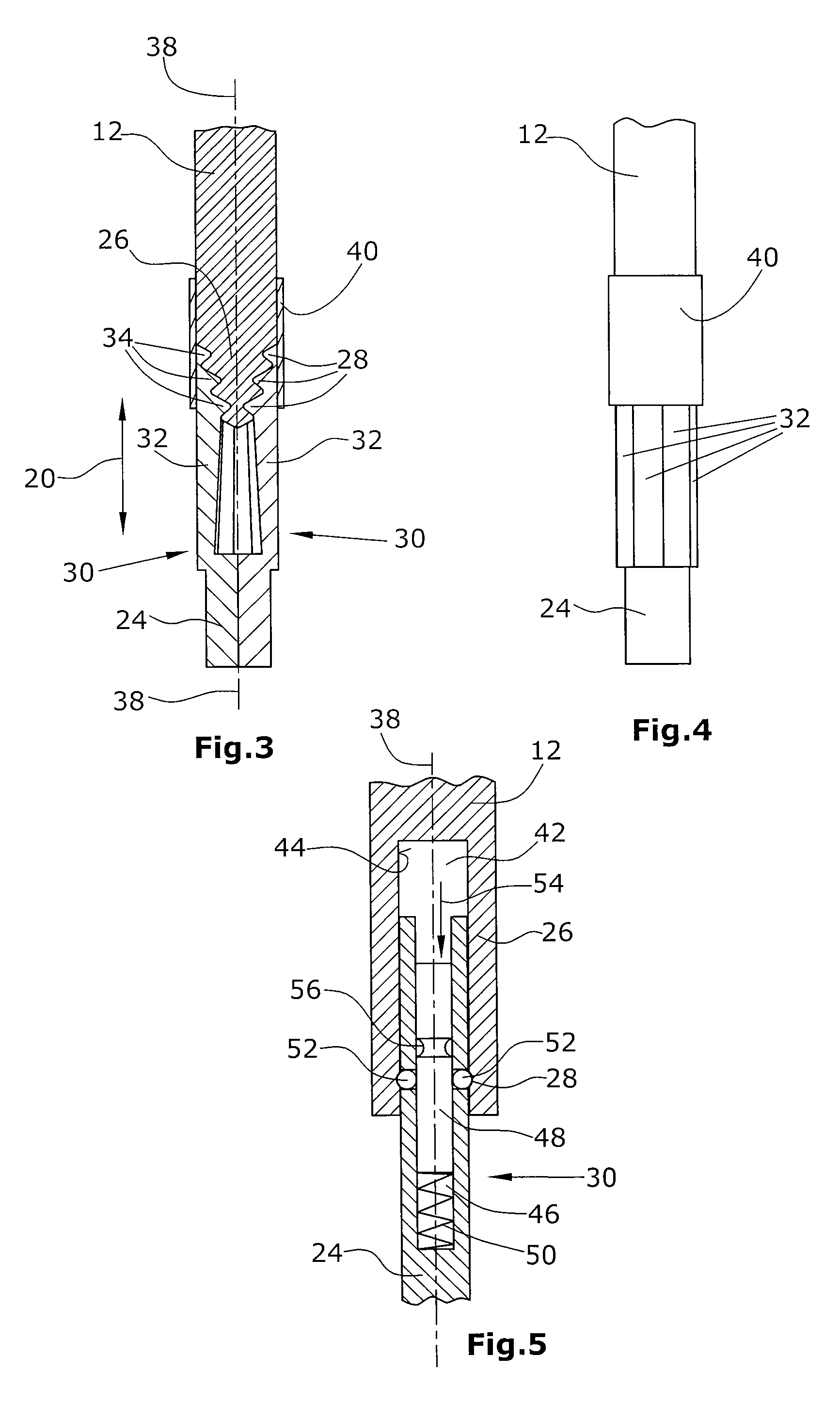
[0030]FIG. 3 is a schematic sectional view of a part of a first preferred embodiment of a coupling device,

[0031]FIG. 4 is a schematic top plan view on the portion of the coupling device illustrated in FIG. 2,

[0032]FIG. 5 is a schematic sectional view of another embodiment of a portion of a coupling device,

[0033]FIG. 6 is a schematic perspective view of a further embodiment of a coupling device in the uncoupled state,

[0034]FIG. 7 is a schematic perspective view of the coupling device illustrated in FIG. 6, the coupling device being in the coupled state,

[0035]FIG. 8 is a schematic perspective view of a further embodiment of a coupling device in the uncoupled state, and

[0036]FIG. 9 is a schematic pe...


PUM


Abstract

A surgical manipulation instrument which is particularly suitable for minimal invasive surgery, comprising an extra-corporeal drive device and a partial intra-corporeal manipulator part. The drive device comprises several axially displaceable first actuation elements. The first actuation elements are detachably connected to axially displaceable second actuation elements, by a coupling device, the second actuation elements being used to actuate an end effector. The coupling device comprises two coupling elements, one of the coupling elements having undercut recesses in which the second coupling element engages.

Description

BACKGROUND[0001]1. Field of the Disclosure[0002]The disclosure refers to a surgical manipulation instrument comprising a coupling detachably connecting an extra-corporeal drive portion and a partially intra-corporeal manipulator part.[0003]2. Discussion of the Background Art[0004]Surgical instruments that are not designed for single use, but for multiple use, have to be sterilized after each single use. Sterilizing can be performed using non-thermal or thermal methods. In everyday clinical practice, sterilizing is generally performed using thermal methods, in particular the so-called autoclaving. In autoclaving, the instrument to be sterilized is exposed for a certain time to water vapor under very high pressure which must wet all surfaces to be sterilized. In the autoclave, the instrument to be sterilized is exposed to temperatures up to 156° C. and pressures up to 2 bar for a period of up to 40 min. Autoclaving must be repeated after each use of the instrument so that in the cours...

Claims


Application Information

Patent Timeline
Patent Type & Authority Patents(United States)
IPC IPC(8): A61B19/00A61B17/00A61B17/29
CPCA61B17/2909A61B17/29A61B2017/00464A61B2017/2922A61B2019/4868A61B2090/0813
Inventor SEIBOLD, ULRICHTHIELMANN, SOPHIE
Owner DEUTSCHES ZENTRUM FUER LUFT & RAUMFAHRT EV
Why Eureka
Try Eureka