Passive optical network system, optical line terminal, and optical network unit

a technology of optical network and optical line terminal, which is applied in the field of passive optical network system with power saving function, optical line terminal, optical network unit, etc., can solve the problems of inability to maintain equipment operation, lack of electric power supply capacity for operating optical access transmission equipment, and large power consumption of relay units on the transmission path. achieve the effect of reducing power consumption, reducing transmission rate, and reducing communication

Inactive Publication Date: 2015-02-03
HITACHI LTD
View PDF10 Cites 8 Cited by
  • Summary
  • Abstract
  • Description
  • Claims
  • Application Information

AI Technical Summary

Benefits of technology

[0012]An aspect of the present invention provides the passive optical communication system capable of keeping a minimum communication by decreasing the transmission rate in each of ONUs to reduce the power consumption. In addition, an aspect of the present invention provides the passive optical communication system in which the user data does not drop out while the transmission rate is changed.
[0016]To avoid drop out of the user data while the clock rate is changed, the clock rate change should be done at a time interval for which the communication with the corresponding ONU is not performed. Because the signal receiving circuit in the ONU has assumption that a continuous signal is received, to receive a signal having a different clock rate, it is necessary to cope with the change in the clock rate by switching AGC (automatic gain control) circuits and CDR (clock data recovery) circuits forming the signal receiving circuit and changing control time constants. In addition, there may be a case where it becomes necessary to change a constant of a PLL (phase-locked loop) supplying the clock to the logic LSI (Large Scale Integrated Circuit) for processing the signal. These circuits need time for a lock-in state by several clock cycles at shortest, and about several tens thousands clock cycles at longest to reach stabilization of the signal condition (lock-in state) from the initial state. Then, the OLT interchanges orders of the transmission signals toward each ONU to arrange signals having the same clock rate at the same time for respective ONUs. This decreases a frequency in that signals of which clock rates have been changed are inputted to the receiving unit of the ONU, so that ratio of time interval for lock-in state, which is an invalid time interval, occupying a total transmission interval can be suppressed. In addition, transmitting a non user signals such as a non-signal time interval, an idle signal, or alternation signal of “0” and “1” is transmitted at a border to avoid dropout of the user data by switching the clock rate for time period of the border.
[0017]An aspect of the present invention provides a passive optical network system capable of maintaining a minimum necessary communication function for effectively using a restricted electric power in a case where a power failure or a power saving are forced by a widespread disaster or a failure in power supply function.

Problems solved by technology

With increase in the communication rate (speed) in the PON, a power consumption of a relay unit on the transmission path tends to be larger.
When a power failure or a power saving are forced by a widespread disaster or a failure, etc. in a power supplying function, the electric power supplying capacity for operating the optical access transmission equipment becomes lack, so that operation of the equipment cannot be maintained.
However, because the existing PON are designed to operate a preset clock frequency, both JP 2008-113193 and JP 2009-260970 do not disclose that the transmission rate is decreased in accordance with the power supplying state.

Method used


Image

  • Passive optical network system, optical line terminal, and optical network unit
  • Passive optical network system, optical line terminal, and optical network unit
  • Passive optical network system, optical line terminal, and optical network unit

Examples


Embodiment Construction

[0049]With reference to drawings will be described embodiments of the present invention.

[0050]In this embodiment, the Ethernet Passive Optical Network (EPON) system defined in IEEE802.3 standard is exemplified. However, the present invention is readily applied to other passive optical network (hereinafter referred to as PON) having a different transmission rate (speed), such a Gigabit Capable PON (GPON) defined by ITU-T Recommendation G.984 series, XGPON (10 G PON) defined by ITU-T Recommendation G.987 series.

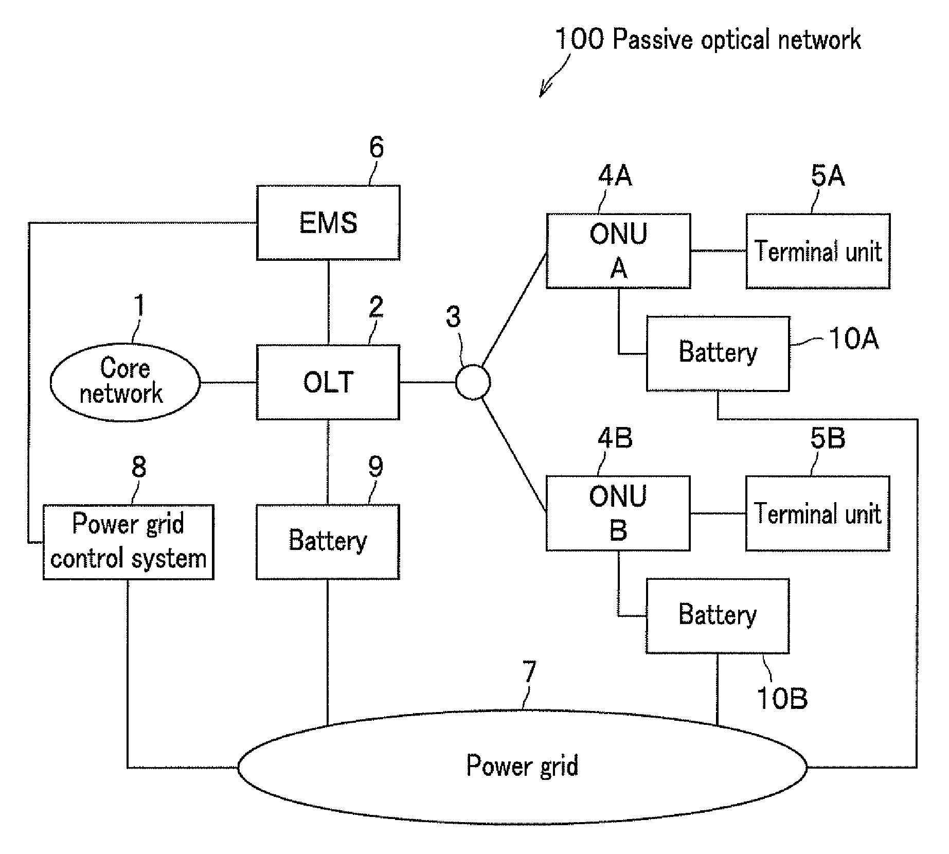
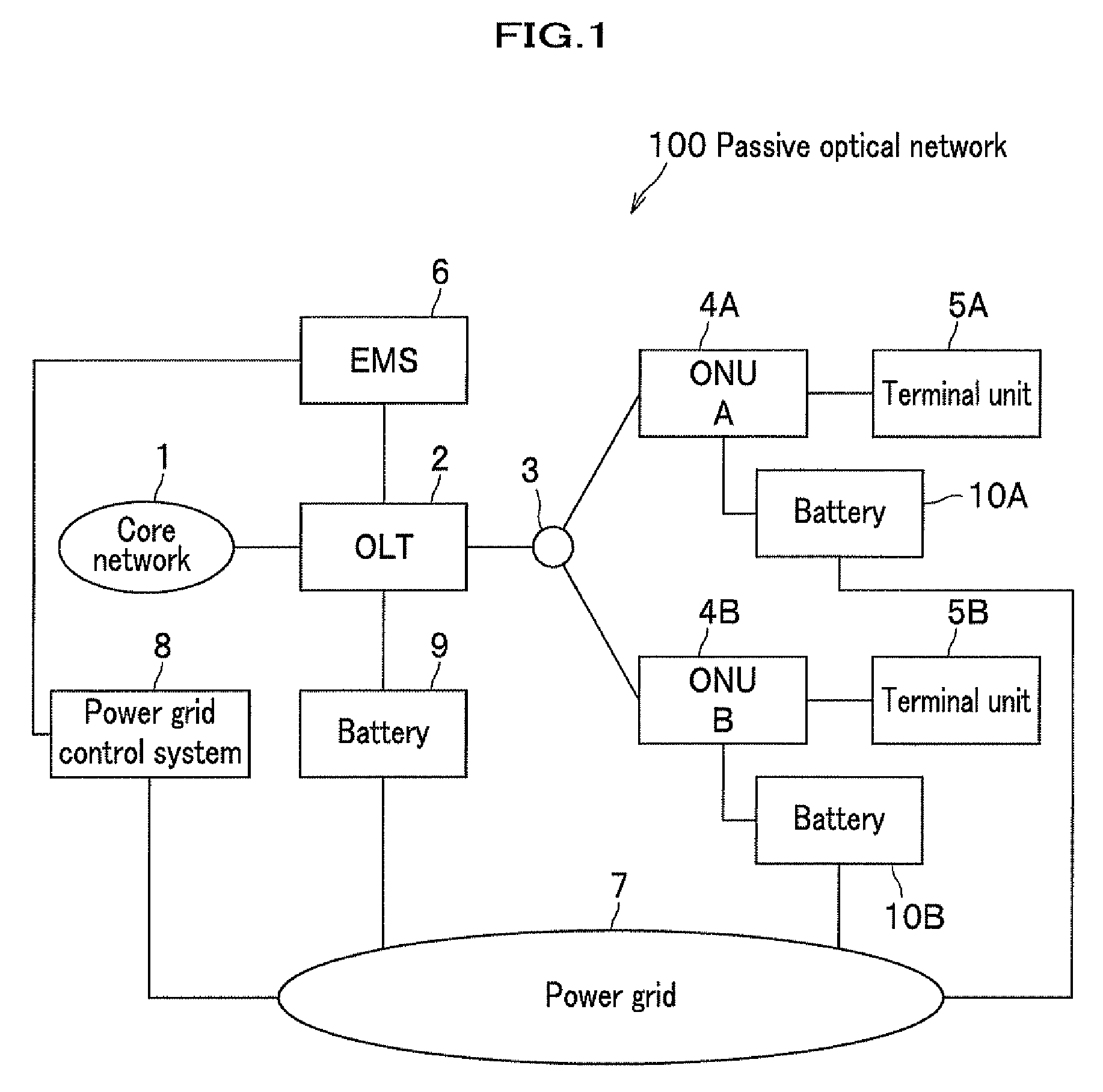
[0051]FIG. 1 is a block diagram of a passive optical network (PON) system according to the present invention to show a network configuration example.

[0052]A passive optical network (PON) system 100 includes an optical line terminal (OLT) 2 and optical network units (ONU) 4 (4A, 4B) connected to the OLT 2 through optical fibers via an optical splitter 3. The OLT 2 is connected to a core network 1. Terminal units 5 (5A, 5B) are connected to the ONUs 4 (4A, 4B), respectively. In F...


PUM


Abstract

An optical line terminal includes the transmission rate control table for storing a minimum bandwidth for an emergency status for each of optical network units in addition to a maximum assigned bandwidth in a normal status. When a decrease in a supply power is detected, the optical line terminal calculates a transmission clock rate providing a minimum bandwidth required by each optical network unit with reference to the transmission rate control table. The optical line terminal determines change timing of downstream and upstream transmission clock rates, and change timing of upstream data for time-division multiplexing to instruct each of the optical network units. Both the optical line terminal and the optical network unit change the transmission clock rates with substantial synchronization therebetween.

Description

CROSS REFERENCE TO RELATED APPLICATION[0001]The present application is based on Japanese application JP 2011-267693 filed on Dec. 7, 2011, the content of which is hereby incorporated by reference into this application.BACKGROUND OF THE INVENTION[0002]1. Field of the Invention[0003]The present invention relates to a passive optical network system with a power saving function, an optical line terminal, and an optical network unit.[0004]2. Description of the Related Art[0005]There are increasing demands for a high speed transmission and a broader band communication in network communication. To meet such demands, introduction of optical networks are planed. The Optical network is a network providing a point-to-point communication between an optical line terminal (hereinafter referred to as OLT) and an optical network unit (hereinafter referred to as ONU) through optical fibers. The passive optical network (hereinafter referred to as PON) forms a network providing a star type of point-to...

Claims


Application Information

Patent Timeline
Patent Type & Authority Patents(United States)
IPC IPC(8): H04Q11/00H04J14/00H04B10/27H04B10/272
CPCH04B10/27H04B10/272H04Q11/0067H04Q2011/0064H04Q2011/0079
Inventor KAZAWA, TOHRUTERAMOTO, TOYOMIMATSUOKA, MAKOTO
Owner HITACHI LTD
Why Eureka
Try Eureka