Apparatus for extracting power from fluid flow

a technology of fluid flow and apparatus, applied in the field of renewable energy, can solve the problems of limited turbine scale, significant restrictions on the scale of turbines, and the gain of additional power extracted from greater size is not offset by the cost of addressing an increase in destructive forces, so as to reduce the cost of the power extraction apparatus, increase the effect of power extraction, and less structural suppor

Active Publication Date: 2015-02-10
AIRLOOM ENERGY INC
View PDF49 Cites 8 Cited by
  • Summary
  • Abstract
  • Description
  • Claims
  • Application Information

AI Technical Summary

Benefits of technology

[0011]By facing the suction surface toward the track, the track may be oriented so that the airfoil moves crosswind with respect to an atmospheric wind speed. This crosswind motion may advantageously allow the airfoil to travel at speeds greater than the speed of the atmospheric wind. Further, by positioning the first elongate section above the second elongate section, an airfoil traveling on either of the sections will directly receive the atmospheric wind; that is, the incident wind on an airfoil is not disturbed by airfoils on the other elongate section. This may allow for increased power extraction.
[0012]In some further examples, a bridle is coupled to the track and anchored to the ground. Bridling may beneficially allow for less structural support, reducing the cost of the power extraction apparatus.
[0013]Bridling may also beneficially allow for reductions in destructive forces on the apparatus. For example, three or more bridles may be distributed along an elongate section to reduce the moment on a length of the elongate section.
[0016]In some examples, the track includes a terminal connecting the first and second elongate sections, where the airfoil decelerates when the airfoil transitions from the first elongate section to the terminal and accelerates when the airfoil transitions from the terminal to the second elongate section. This may eliminate high forces attendant with the change in direction. The deceleration of the airfoil may also be harvested as power.

Problems solved by technology

This “square-cube” law places significant restrictions on the scale of turbines.
Inevitably, the gain of additional power extracted from greater size is not offset by the cost of addressing an increase in destructive forces.
For at least this reason, turbine scale is limited.
Thus, the power extracted may never equal the available power.
In addition, the tether will create drag as it moves through the air, slowing the kite, and thus reducing the harvested power.
Finally, high-flying AWEs are subject to aviation restrictions, which limit their geographic scope (due to no-fly zones, for example) and present regulatory hurdles for implementation.

Method used


Image

  • Apparatus for extracting power from fluid flow
  • Apparatus for extracting power from fluid flow
  • Apparatus for extracting power from fluid flow

Examples


Embodiment Construction

[0033]In the following description of embodiments, reference is made to the accompanying drawings which form a part hereof, and in which it is shown by way of illustration specific embodiments which can be practiced. It is to be understood that other embodiments can be used and structural changes can be made without departing from the scope of the disclosed embodiments.

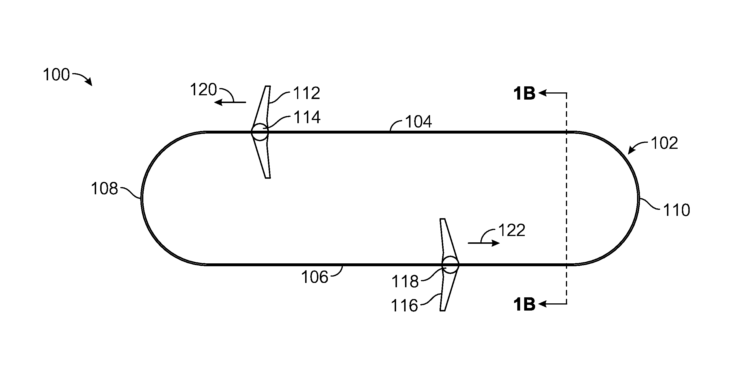
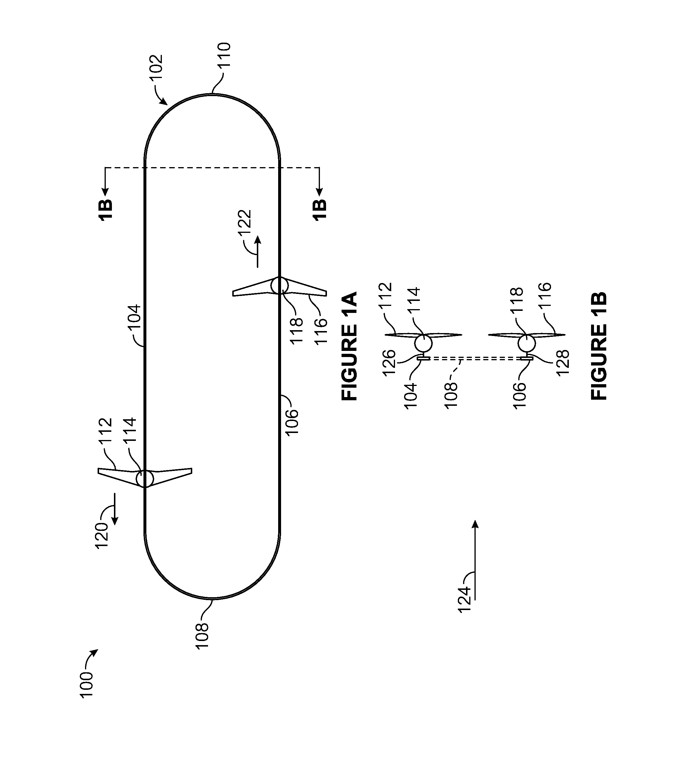
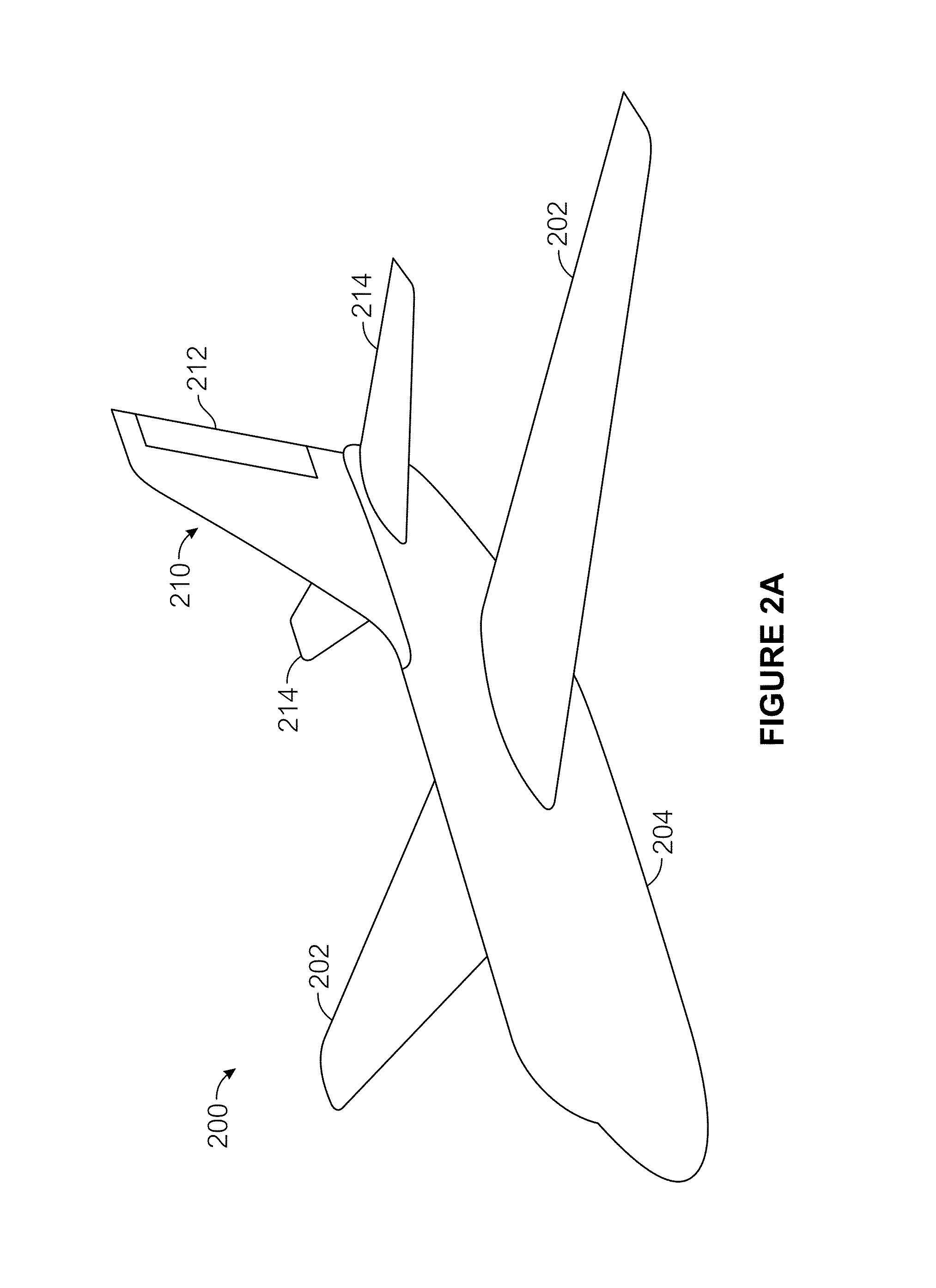
[0034]Examples of the disclosure are apparatuses that include a track and an airfoil coupled to the track. The track includes first and second elongate sections, where the first elongate section is positioned above the second elongate section. The airfoil includes a pressure surface lying between a suction surface and the track, and is moveable in opposite directions when alternately coupled to the first elongate section and second elongate section.

[0035]In some examples, methods of extracting power include providing a track, positioning the track, coupling an airframe to the track, and harvesting power from an atmosp...


PUM

PropertyMeasurementUnit
relative anglesaaaaaaaaaa

Abstract

An apparatus for extracting power includes a track and an airfoil coupled to the track. The track includes first and second elongate sections, where the first elongate section is positioned above the second elongate section. The airfoil includes a pressure surface lying between a suction surface and the track, and is moveable in opposite directions when alternately coupled to the first elongate section and second elongate section.

Description

FIELD OF THE DISCLOSURE[0001]This disclosure generally relates to renewable energy. More specifically, this disclosure describes apparatuses and methods for extracting power from fluid flow.BACKGROUND OF THE INVENTION[0002]Extracting power from fluid flow is a prominent source of renewable energy. Mainstream examples include wind power and hydropower.[0003]Traditional systems for extracting power from fluid flow are primarily turbine-based. In a turbine, one or more blades are rotatable about a central point, which is rigidly attached to an anchor (typically a tower). The blades are placed within the flowing fluid, which induces a rotation of the blades, and the rotation is converted to electricity.[0004]Turbines may suffer from a number of drawbacks. For example, the forces exerted on a turbine are proportional to the cube of the length of the turbine blades. As the turbine blades increase in size, destructive forces (the moment about a tower, for example) are cubed. By contrast, u...

Claims


Application Information

Patent Timeline
Patent Type & Authority Patents(United States)
IPC IPC(8): B64C31/06
CPCF03D9/25F03D13/10F03D13/20F03B17/06F03D5/04F03D7/022F05B2240/921F05B2240/917F05B2240/912F05B2210/16F05B2230/60Y10T29/49321Y02E10/728Y02E10/70Y02E10/20Y02E10/72Y02P70/50Y02E10/30F03D7/00
Inventor LUMLEY, ROBERT
Owner AIRLOOM ENERGY INC
Why Eureka
Try Eureka