Spinal implant with a lockable ball joint

a technology of ball joint and implant, which is applied in the field of spine implants, can solve the problems of surgeons not being able to lock, the ball joint connection cannot be locked, and the implant manufacturer must double the number of product lines, so as to achieve the effect of simplifying the use of the implan

Active Publication Date: 2015-02-10
EUROS
View PDF17 Cites 44 Cited by
  • Summary
  • Abstract
  • Description
  • Claims
  • Application Information

AI Technical Summary

Benefits of technology

[0028]The object of the present invention is to propose a spinal implant able to provide a single-axis implant function and a multi-axis implant function in order to facilitate the work of the surgeon and to prevent duplication of the costs of manufacturing, storing, and managing the implants.
[0030]Accordingly, by means of the invention, when the locking member is not in the locking position the implant behaves as a multi-axis implant. In contrast, when the locking member is in the locking position the implant behaves as a single-axis implant. Consequently, a single type of spinal implant enables the surgeon to treat all traumas of the vertebral column.
[0032]Moreover, the surgeon may choose which type of implant to fit to the vertebral column of the patient during the surgical operation itself, with the benefit of simplifying use of the implant.

Problems solved by technology

There is a drawback in that the implant manufacturer must double the number of product lines to offer both types of spinal implant that surgeons need to operate on patients.
The drawback of the above implant is that the ball-joint connection can be locked only after the connecting rod has been engaged in the implant.
Thus the surgeon is not able to lock it before operating on the patient.
Thus the surgeon is not able to lock the multi-axis function while operating on the patient.

Method used


Image

  • Spinal implant with a lockable ball joint
  • Spinal implant with a lockable ball joint
  • Spinal implant with a lockable ball joint

Examples


first embodiment

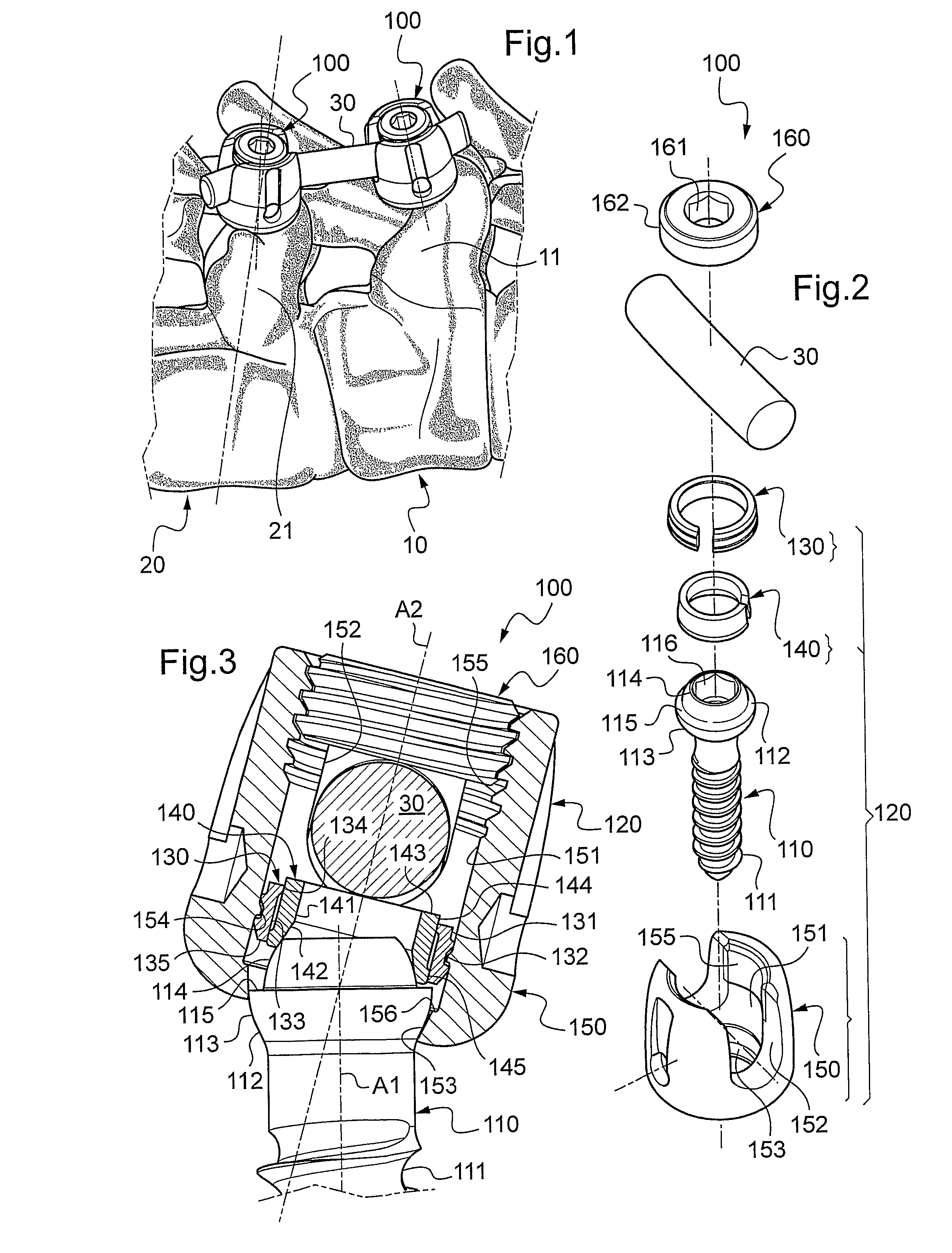
[0056]FIG. 2 is an exploded view of one of the spinal implants from FIG. 1 in the invention;

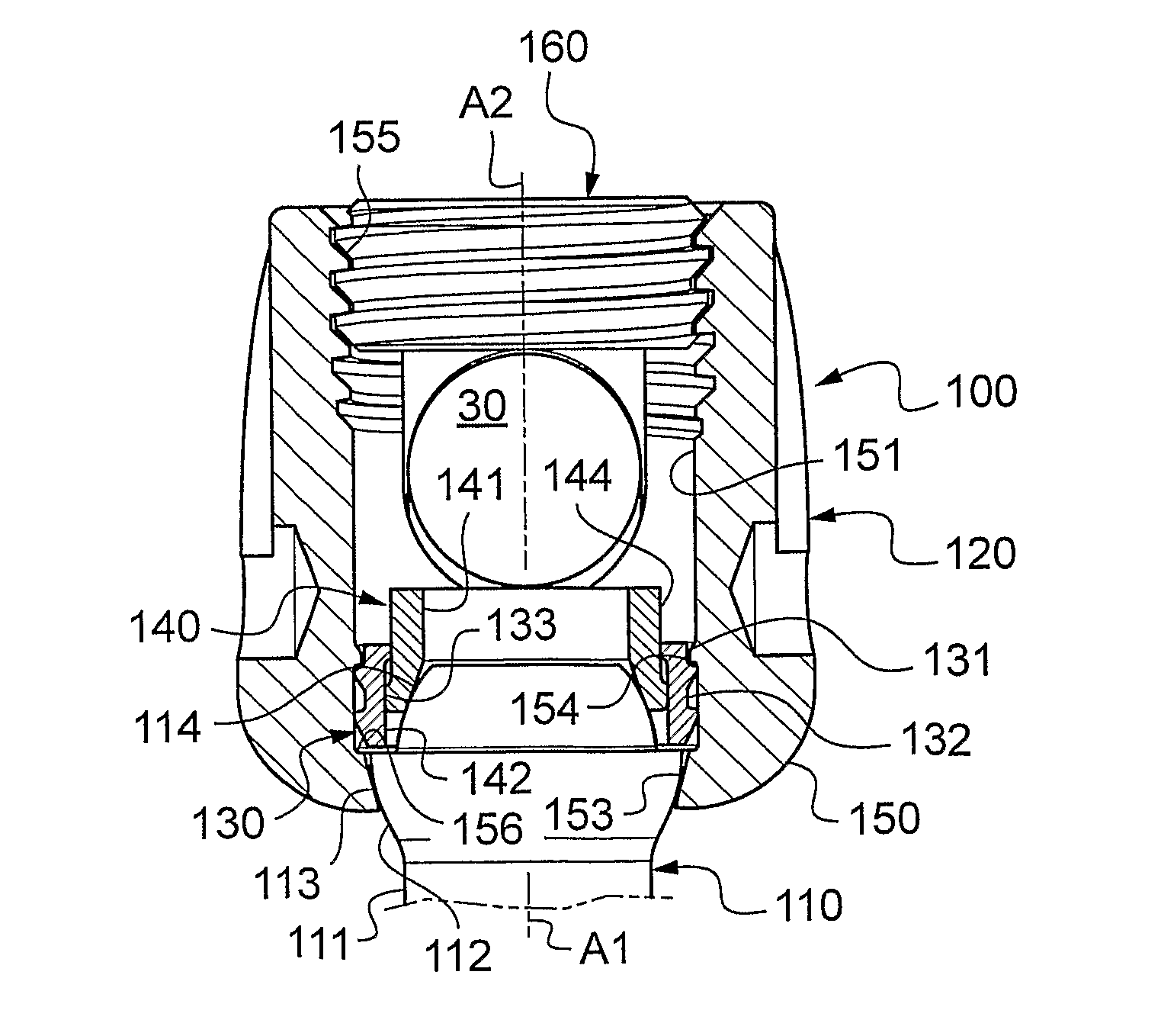
[0057]FIG. 3 is a view in axial section of the spinal implant from FIG. 2, in which the ball-joint connection is left free;

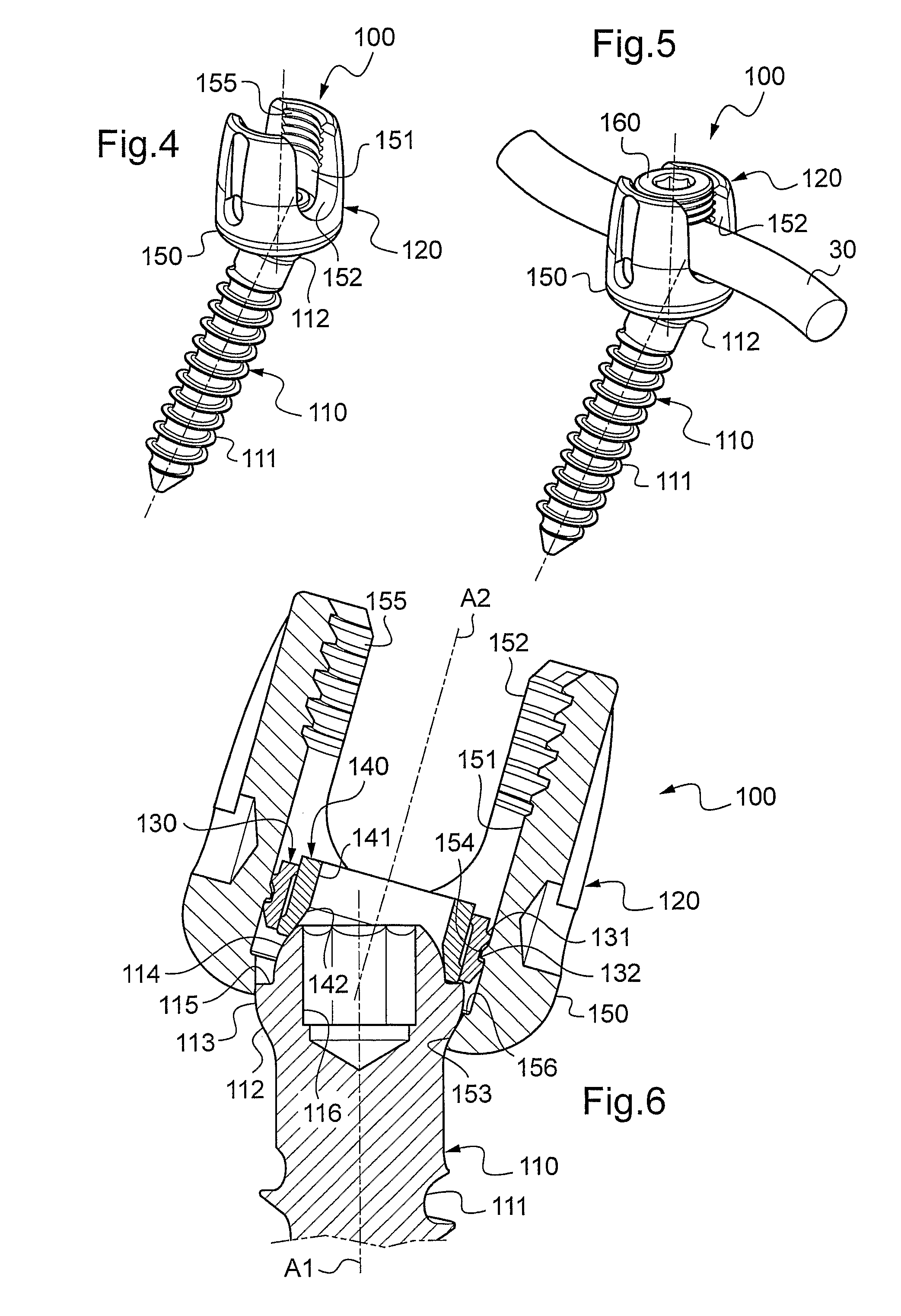
[0058]FIGS. 4 and 5 are perspective views of the spinal implant from FIG. 3, alone and equipped with a locking screw for the connecting rod;

[0059]FIGS. 6 to 8 are diagrams showing the operation of locking the spinal implant from FIG. 2;

[0060]FIG. 9 is a view in axial section of the spinal implant from FIG. 2 in which the ball-joint connection is locked to provide a pivot connection;

[0061]FIGS. 10 and 11 are perspective views of the spinal implant from FIG. 9, alone and equipped with a locking screw for the connecting rod;

second embodiment

[0062]FIG. 12 is an exploded view of one of the spinal implants from FIG. 1 in the invention;

[0063]FIG. 13 is a perspective view of the spinal implant from FIG. 12 and a locking tool;

[0064]FIG. 14 is a view in axial section of the spinal implant from FIG. 12 in which the ball-joint connection is left free;

[0065]FIG. 15 is a view in axial section of the spinal implant from FIG. 14 and the locking tool in which the ball-joint connection is locked to provide a pivot connection;

third embodiment

[0066]FIG. 16 is an exploded view of one of the spinal implants from FIG. 1 in the invention;

[0067]FIG. 17 is a view in axial section of the spinal implant from FIG. 16 in which the ball-joint connection is left free;

[0068]FIG. 18 is a view in axial section of the spinal implant from FIG. 16 in which the ball-joint connection is locked to provide a pivot connection;


PUM


Abstract

A spinal implant (100) includes an anchoring part (110) adapted to be anchored to a vertebra and having first connecting elements (112), and a mounting part (120) including both an internal axial housing (151) to receive transversely a connecting rod (30), this axial housing being terminated beside the anchoring part (110) by a bottom (156), and also second connecting elements that cooperate with the first connecting elements to form a ball-joint connection between the anchoring part and the mounting part. The spinal implant includes retaining elements that are situated near the bottom of the axial housing of the mounting part that are adapted to fasten a locking member in a stationary so-called locking position in which the ball-joint connection formed by the first and second connecting elements is locked to fasten the anchoring part and the mounting part in rotation relative to each other about at least two orthogonal axes.

Description

TECHNICAL FIELD TO WHICH THE INVENTION RELATES[0001]The present invention relates generally to spinal implants intended to immobilize at least two vertebrae relative to each other.[0002]It relates more particularly to a spinal implant including:[0003]an anchoring part adapted to be anchored to a vertebra and including first connecting means; and[0004]a mounting part comprising, both an internal axial housing open to the outside via two facing lateral openings in the form of cradles for receiving transversely a connecting rod, this axial housing being terminated beside the anchoring part by a bottom, and also second connecting means that cooperate with said first connecting means to form a ball-joint connection between said anchoring part and said mounting part.TECHNOLOGICAL BACKGROUND[0005]Spinal implants of the above-mentioned type are used in pairs and in combination with a connecting rod to treat arthrosis and vertebral fractures or to correct distortions of the vertebral column ...

Claims


Application Information

Patent Timeline
Patent Type & Authority Patents(United States)
IPC IPC(8): A61B17/86A61B17/70A61B17/88
CPCA61B17/7037A61B17/7076A61B17/7032A61B17/8875
Inventor GENNARI, JEAN-MARIECHATAIGNER, HERVEVITAL, JEAN-MARCNOGUES, LAURENTMOUSSELARD, HUGUES-PASCALKOUYOUMDJIAN, PASCALTAILLET, JEAN-MICHELTISSERAND, PHILIPPE
Owner EUROS
Why Eureka
Try Eureka