Distributed digital antenna system

a distributed antenna and digital antenna technology, applied in the field of communication, can solve the problems of large base station antennas that may not fit within an area either physically or aesthetically, and the placement of additional base stations where these coverage holes are located is not always an option, and the effect of increasing the number of base stations

Active Publication Date: 2015-02-17
COMMSCOPE TECH LLC
View PDF187 Cites 89 Cited by
  • Summary
  • Abstract
  • Description
  • Claims
  • Application Information

AI Technical Summary

Problems solved by technology

Placing additional base stations where these coverage holes are located is not always an option.
Base stations tend to be very expensive due not only to the cost of the equipment but also because of land acquisition costs.
Additionally, large base station antennas may not fit within an area either physically or aesthetically.
One solution to hole coverage is to use smaller remote antennas whe

Method used


Image

  • Distributed digital antenna system
  • Distributed digital antenna system
  • Distributed digital antenna system

Examples


Embodiment Construction

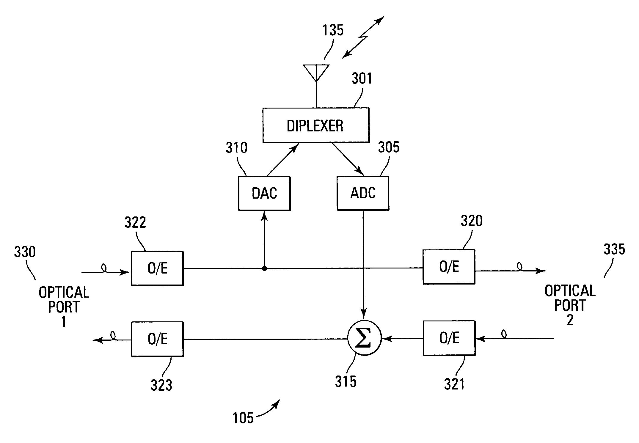
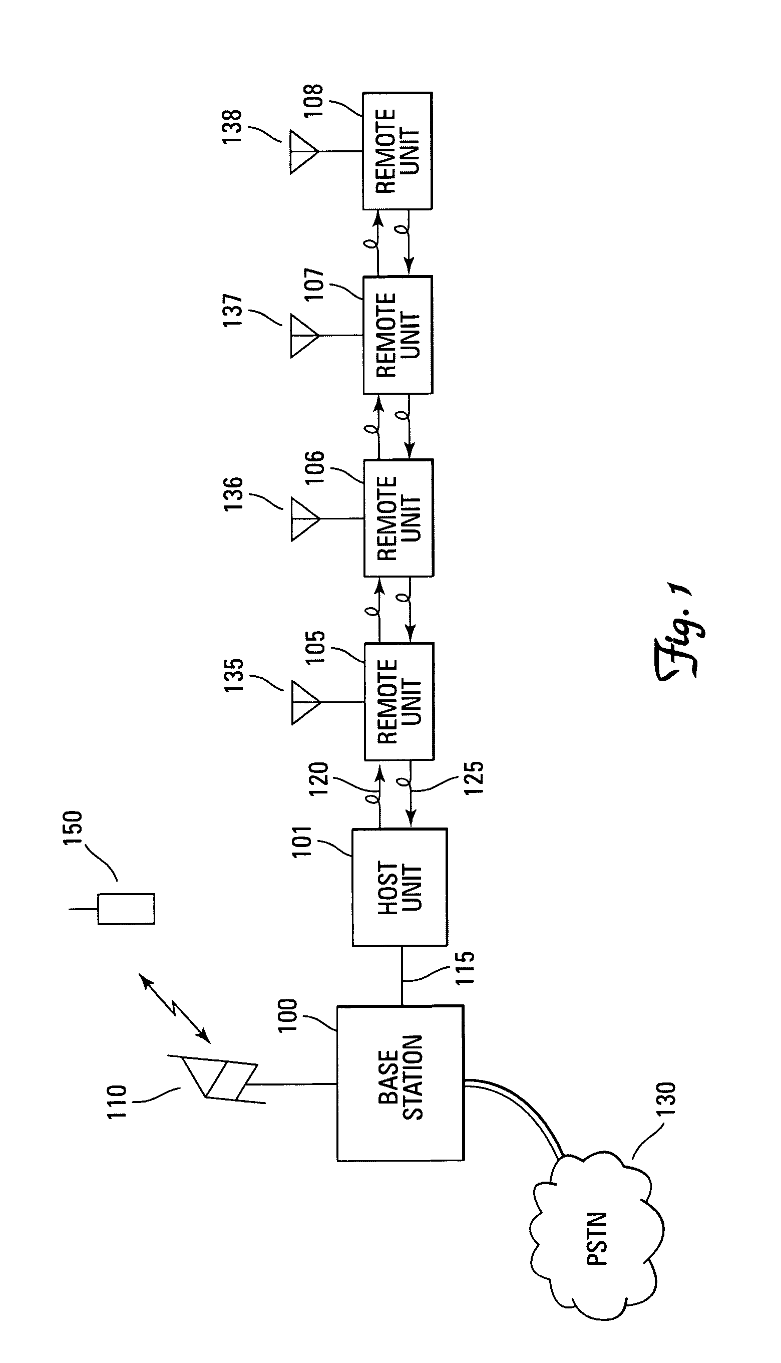
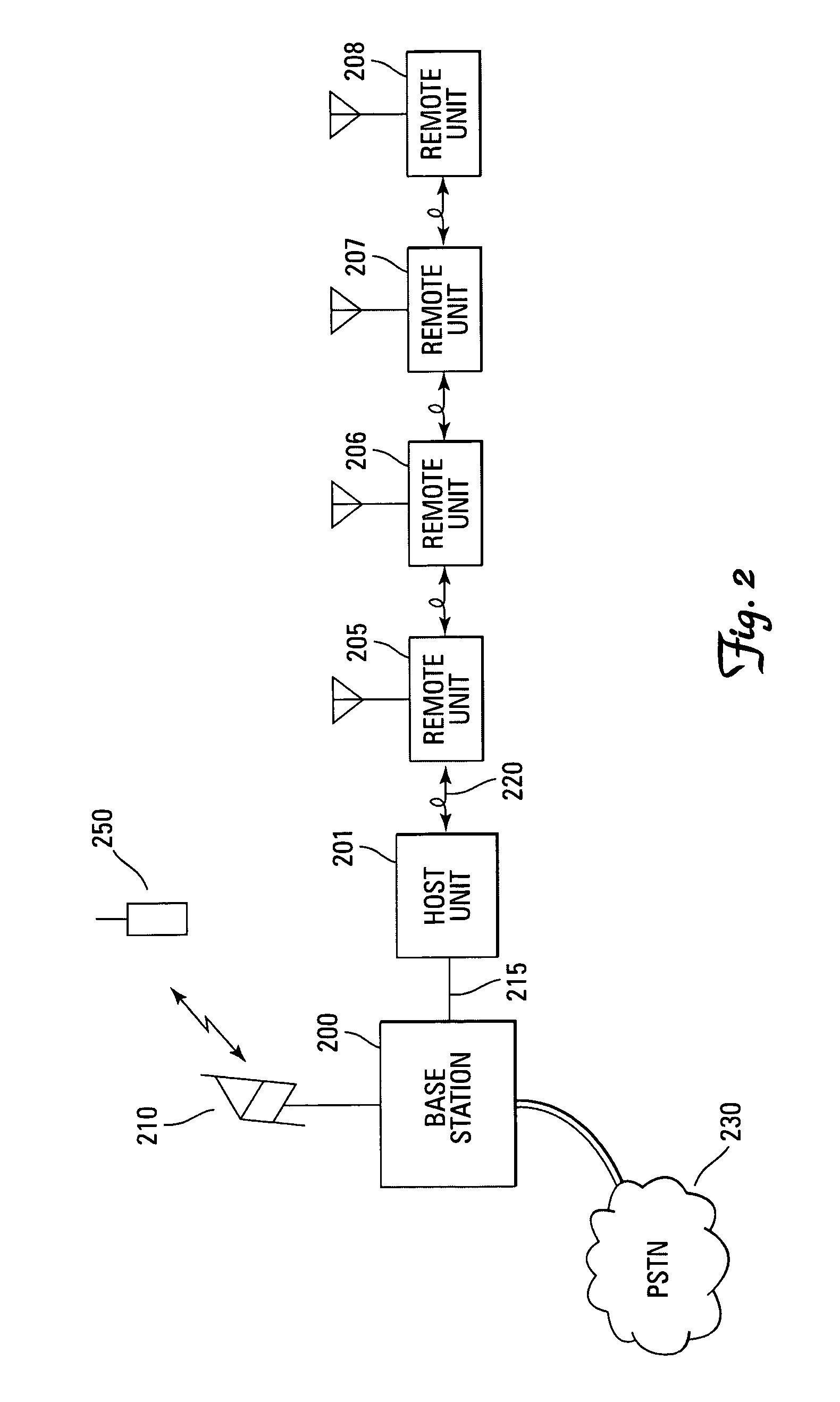
[0012]The embodiments of the present invention provide a digital distributed antenna system that enables a communication system to fill coverage holes without the expense of additional base stations. This is accomplished by distributing a fiber optic cable through the area in which coverage is desired and tapping into the fiber at desired antenna locations.

[0013]The embodiments of the present invention refer to fiber optics as a means of communication between remote units and the host unit. However, any optical medium, such as a laser through the air, can be substituted for the optical fiber.

[0014]FIG. 1 illustrates a block diagram of one embodiment of a distributed digital antenna system of the present invention. The system has a base station (100) that communicates over an RF link using an antenna (110). The base station communicates over the RF link using any appropriate air interface standard. For example, the air interface standard comprises one of Advanced Mobile Phone System ...


PUM


Abstract

An optical medium, such as fiber, is tapped to provide an antenna port wherever radio service coverage is desired. Each antenna port is a bi-directional remote unit that receives a digital optical signal from a host unit and transforms the signal to a radio frequency signal for transmission by the remote unit. The remote unit receives radio frequency signals that are converted to digital signals and summed with signals from other remote units and converted to an optical signal for transmission to the host unit.

Description

RELATED APPLICATION[0001]This application claims priority to U.S. Provisional Patent Application Ser. No. 60 / 430,434 filed Dec. 3, 2002, and titled “Distributed Digital Antenna System,” which is commonly assigned and incorporated by reference herein.TECHNICAL FIELD[0002]The present invention relates generally to communications and particularly to communications through a distributed antenna system.BACKGROUND[0003]Various types of wireless communication systems have become prevalent around the world. For example, cellular communication systems cover most major metropolitan areas as well as major highways through remote areas. Cellular systems permit individuals with cellular handsets to communicate with base stations that are connected to the public switched telephone network (PSTN) or some other communication network.[0004]As with any communication system, cellular systems can leave coverage “holes” where the signal from the base stations cannot reach. The holes can be in tunnels, v...

Claims


Application Information

Patent Timeline
IPC IPC(8): H04W4/00G06F1/03H04B10/00H04B10/12H04B10/2575H04W16/26
CPCH04B10/25759H04B10/25755H04W16/26H04B1/40H04W88/085H04B10/25756H04B10/25
Inventor BAUMAN, DONALD R.WALA, PHILIP M.BRENNAN, JEFFREY O.
Owner COMMSCOPE TECH LLC
Why Eureka
Try Eureka