
Power conversion and energy storage device

a technology of energy storage device and power conversion, which is applied in the direction of magnetic circuit rotating parts, magnetic circuit shape/form/construction, greenhouse gas reduction, etc., can solve the problems of not being able to apply heretofore, and achieve the effect of efficient electricity production

Active Publication Date: 2015-02-24
AMERICAN HYDRO JET CORP
View PDF23 Cites 12 Cited by
  • Summary
  • Abstract
  • Description
  • Claims
  • Application Information

AI Technical Summary

Benefits of technology

The present invention is aimed at providing a low-cost hydroelectric power-generating system that can efficiently produce electricity from a low-head dam in a waterway. It also aims to replace the conventional axial flow pump with a low-cost, low-weight, in-line pumping system that can more efficiently pump fluids to economic effect. Additionally, it also aims to produce a low-cost hydroelectric power-generating system that is quick and easy to install, service and replace.

Problems solved by technology

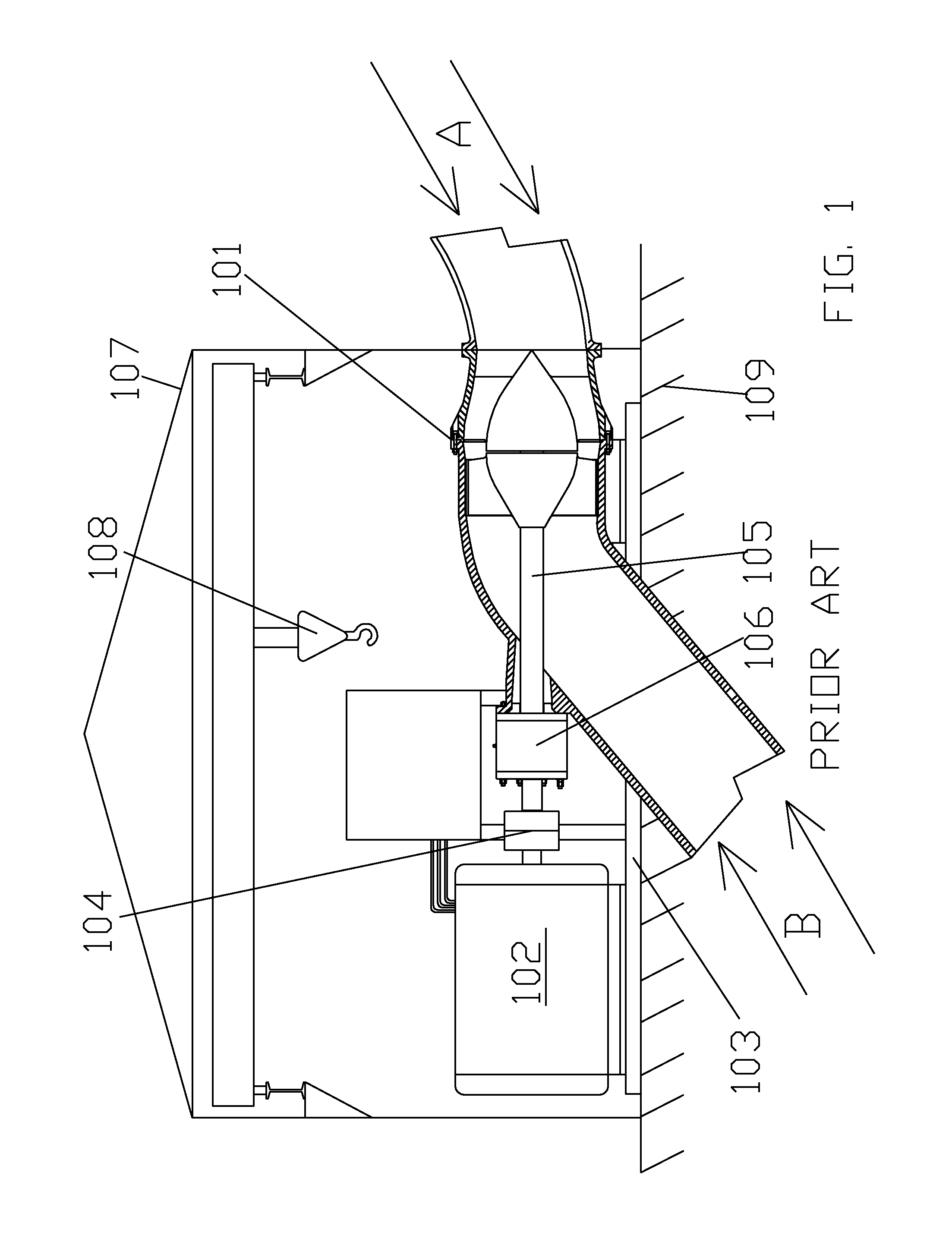
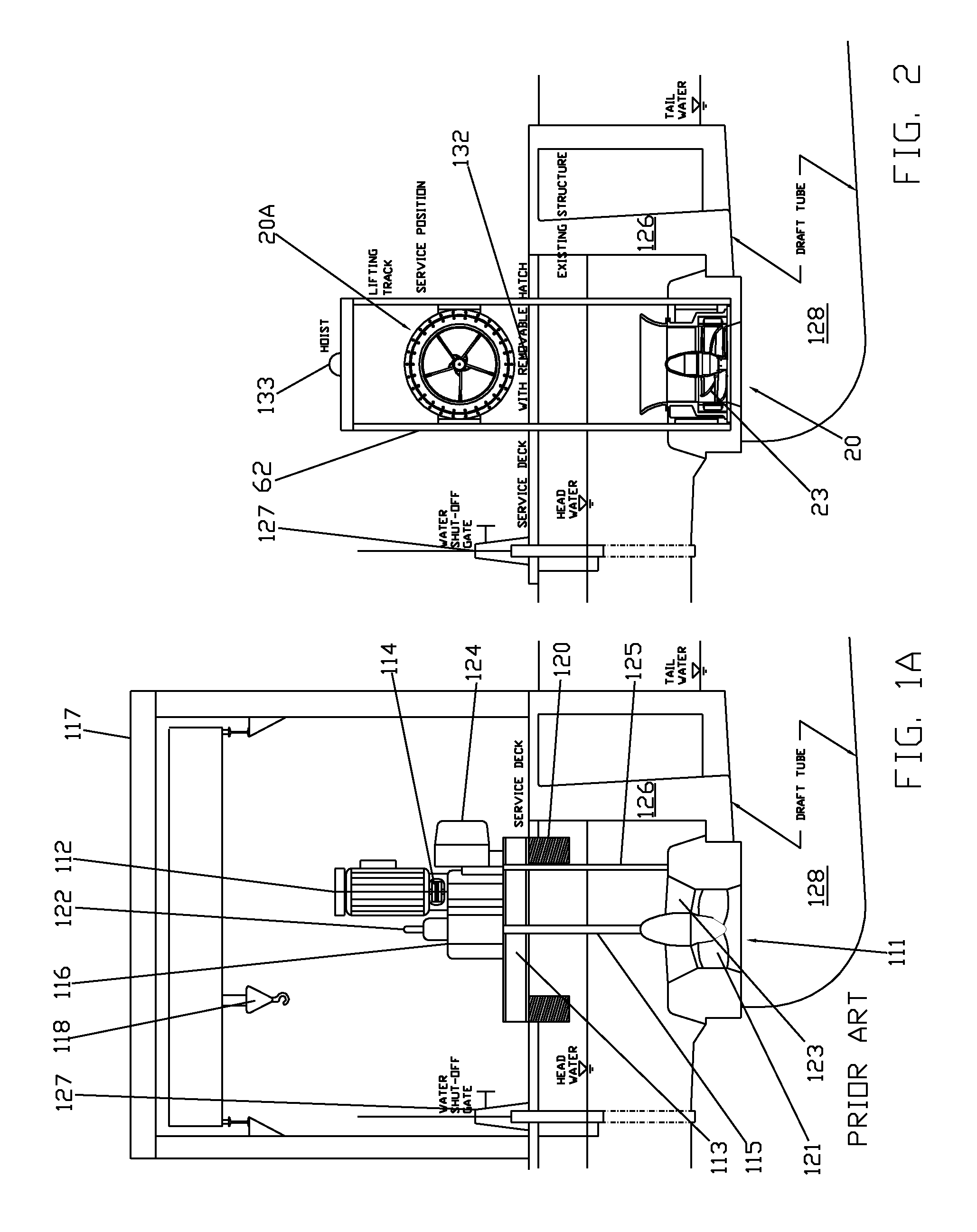
Additionally, the manufacture of the components of power conversion device 20 using composite materials reduces the weight to a fraction of the same metallic components and generally obtains a five-times reduction in weight over conventional systems, permitting applications heretofore impossible because of heavy weight, large dimensions, high cost and large footprint size and often requiring a powerhouse (building).

Method used


Image

  • Power conversion and energy storage device
  • Power conversion and energy storage device
  • Power conversion and energy storage device

Examples


Embodiment Construction

[0127]The following detailed description explains a novel approach to hydroelectric power generation starting with the integration of turbine and generator. This inventive concept, with its quintuple increase in power density, permits application of hydroelectric power generation in situations previously thought impossible by drastically lowering costs of manufacture, installation and maintenance, reducing overall equipment size, and increasing system efficiency.

[0128]Likewise, the same concept can be applied with the identical hardware, without limitation, to the inverse operation of a turbine / generator, namely as a motor / pump. By providing power from an electric power source to the power conversion device, the inventive device will function as a motor and pump. The power density of the power conversion device (five times greater than the prior art) is of equal advantage as a motor / pump and has many applications for industrial, pipeline and marine use. The switching of functions fr...


PUM


Abstract

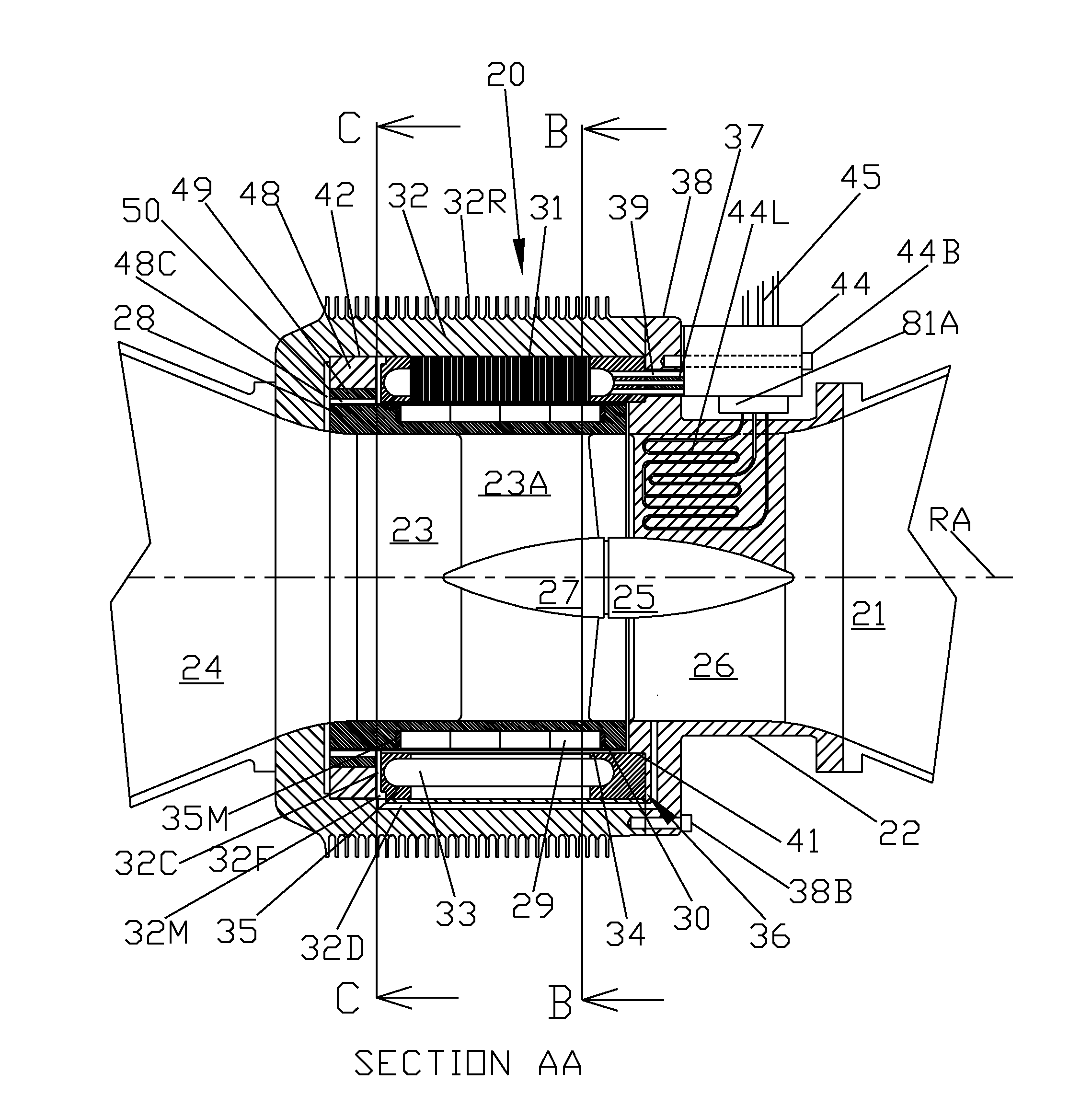
Power conversion device including: a first fluid conduit; a diffuser attached thereto with at least one vane supporting a diffuser hub; a rotor supported by the diffuser hub and having a rotor blade, hub, and shroud at the periphery thereof with at least one magnet thereon; a housing surrounding the shroud and attached to the diffuser, and having a stator including laminations forming poles and at least one coil therearound, the stator encapsulated in a non-metallic compound to prevent fluid contact with laminations and coil(s); a commutation control connected to the coil(s) and having external leads; and a second fluid conduit attached to the housing so fluid flow causes a torque load on the blades, rotating the rotor and inducing a magnetic field in the poles to generate current in the coil, converting hydraulic power to electric power. The device operates as a turbine / generator and as a motor / pump.

Description

RELATED APPLICATIONS[0001]This is a continuation-in-part of U.S. patent application Ser. No. 12 / 691,456, filed on Jan. 21, 2010, the contents of which are herein incorporated by reference.FIELD OF THE INVENTION[0002]This invention relates to low-cost conversion from hydraulic power to electric power and from electric power to hydraulic power.BACKGROUND OF THE INVENTION[0003]Power generation from waterways is well-known and commonly practiced in coastal waters and rivers. A well-known application is in dams with built-in turbines driving generators for the production of electric power. Most navigable waterways have a controlled water level to facilitate shipping by maintaining minimum depths through the placement of dams in the waterway. Shipping is made possible through the location of locks adjacent to the dams.[0004]The Mississippi River is an example of such a waterway with a controlled water level and a system of dams with locks. The water-level drop at most Mississippi River da...

Claims


Application Information

Patent Timeline
Patent Type & Authority Patents(United States)
IPC IPC(8): F03B13/08F03B3/04F03B3/18H02K1/14H02K1/27H02K5/08H02K5/12H02K5/20H02K7/08H02K7/14H02K7/18H02K9/19H02K11/00H02K11/04
CPCF03B3/04F03B3/18F03B13/083H02K1/148H02K1/278H02K5/08H02K5/12H02K7/086H02K7/088H02K7/14H02K7/1823H02K11/0073H02K11/0094H02K11/046H02K5/20H02K9/19H02K2213/12Y02E10/223Y02E10/22H02K5/1285H02K11/33Y02E10/20H02K5/203H02K11/05
Inventor ROOS, PAUL W.
Owner AMERICAN HYDRO JET CORP
Learn More