
Measuring method and device for determining transmission and/or reflection properties

a technology of optical measuring and transmission and reflection, applied in the direction of photometry, instruments, material analysis, etc., can solve the problem of not meeting the requirements

Active Publication Date: 2015-03-03
CARL ZEISS MICROSCOPY GMBH
View PDF12 Cites 3 Cited by
  • Summary
  • Abstract
  • Description
  • Claims
  • Application Information

AI Technical Summary

Benefits of technology

The present methods provide a way to determine the transmission and reflection properties of objects using simpler equipment than previous methods. These methods are particularly useful for quality inspection in manufacturing. They involve measuring the optical properties of a substrate as it moves past two illuminating devices. To minimize the spatial spread of the measured area, the illumination is done in a stroboscopic manner. In another embodiment, the methods include using reference photodetectors and screening means to prevent light from damaging the detectors. Overall, the methods decrease the complexity of optical analysis for various applications.

Problems solved by technology

With the methods and apparatuses available in prior art, this requirement cannot be met.

Method used


Image

  • Measuring method and device for determining transmission and/or reflection properties
  • Measuring method and device for determining transmission and/or reflection properties

Examples


Embodiment Construction

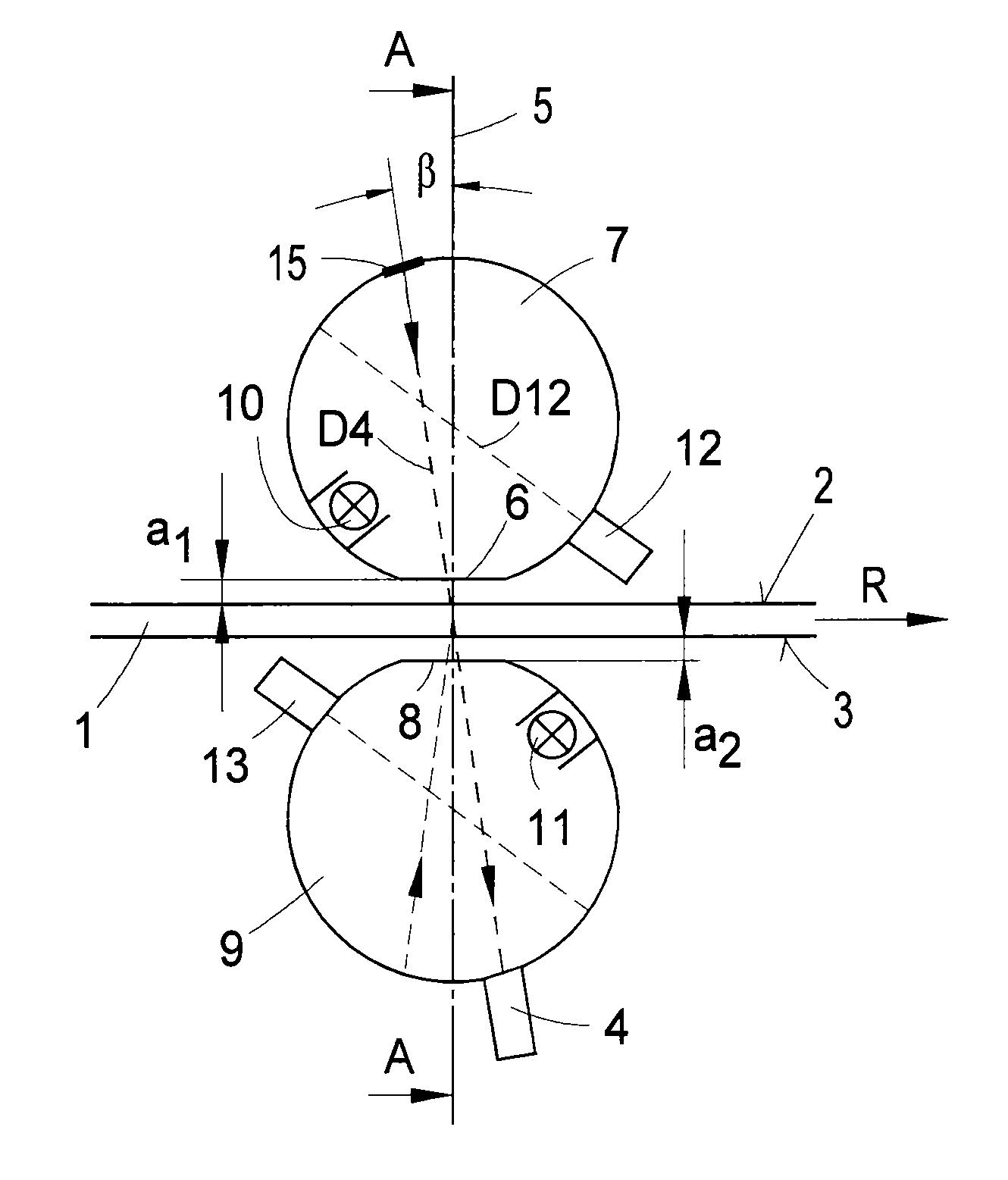
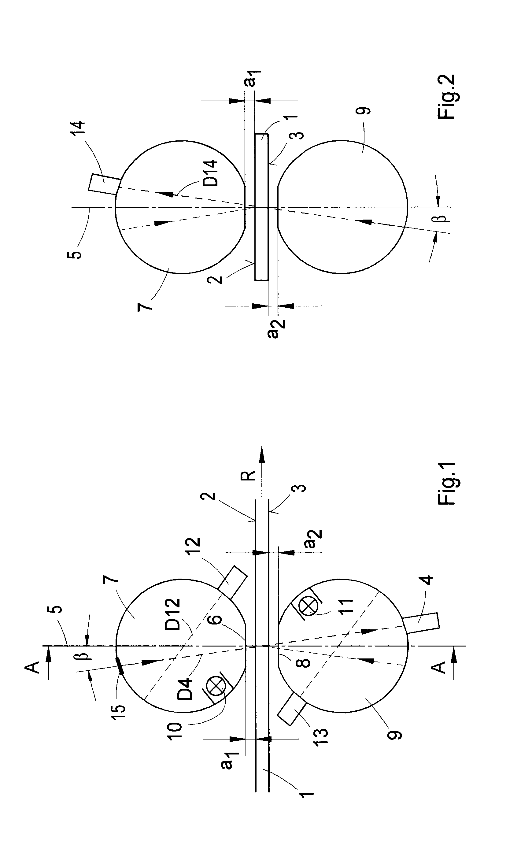
[0053]FIG. 1 symbolically shows a strip-shaped, translucent object 1—here, for example, a substrate which is to be provided with a transparent, electrically conductive coating on its large surface 2 in an inline coating plant. In this process, the object 1 is continually moved in the direction R (indicated by an arrow in FIG. 1), in which, following the coating process, the object passes the present measuring apparatus as shown in FIG. 1.

[0054]In the example depicted in FIG. 1, let the quality inspection refer to the measurement and assessment of the transmission properties of the coated object and to the measurement of the reflectivities of both the coated large surface 2 and the uncoated large surface 3 of the object 1. The measurement is performed periodically while the substrate strip continuously moves past the measuring apparatus.

[0055]For determining the transmission properties, the measuring method to be applied is that specified in the international ASTM D 1003 standard; ac...


PUM

PropertyMeasurementUnit
angleaaaaaaaaaa
angleaaaaaaaaaa
transmissionaaaaaaaaaa

Abstract

The disclosure relates to optical measuring methods and apparatus for determining the transmission and / or reflection properties of translucent objects with utility for process monitoring and quality inspection in the manufacture of surface-coated substrates. According to the disclosure the transmission and reflection properties are determined in such a way that sequentially:a first large surface of the object is illuminated by a first illuminating device, with a photodetector measuring the total transmittance (Ttotal),a second, large surface of the object, lying opposite and parallel to the first one, is illuminated by a second illuminating device, with a photodetector measuring the diffuse transmittance (Tdiffuse), and optionallythe first large surface of the object is illuminated by the first illuminating device, with the photodetector measuring the reflectance, and / orthe second large surface of the object is illuminated by the second illuminating device,with the photodetector measuring the reflectance.

Description

CROSS REFERENCE TO RELATED APPLICATIONS[0001]The present application claims priority to and full benefit of German National Patent Application No. DE 10 2011 077 290.1 filed 9 Jun. 2011 the entire contents of which are incorporated herein by reference.FIELD OF THE DISCLOSURE[0002]The present disclosure relates to optical measuring methods and apparatus for determining the transmission and / or reflection properties of translucent objects; in particular, with utility for process monitoring and quality inspection in the manufacture of surface-coated substrates and objects, especially large-surface objects. disclosureBACKGROUND OF THE DISCLOSURE[0003]In the manufacture of coated translucent materials, such as substrates provided, e.g., with electrically conductive coatings as used in photovoltaics, the inspection of the transparent and reflective properties of the substrate is important mainly with regard to achieving an optimum efficiency in the conversion of solar radiation to electric...

Claims


Application Information

Patent Timeline
Patent Type & Authority Patents(United States)
IPC IPC(8): G01N21/00G01N21/47G01N21/89G01N21/896
CPCG01N21/8901G01N21/474G01N21/896G01N2201/065G01J1/02G01J1/08G01J1/16
Inventor MARGRAF, JOERGLAMPARTER, PETER
Owner CARL ZEISS MICROSCOPY GMBH
Learn More