
Aspirating induction nozzle

a technology of induction nozzle and inlet air, which is applied in the direction of ventilation system, combustion type, heating type, etc., can solve the problems of visual unattractiveness, impairing the performance of the nozzle discharge, and the industry has not yet recognized the effect, so as to reduce the turbulence of the secondary induced ambient air flow, increase the flow of ambient air, and reduce the effect of dilution ratio

Active Publication Date: 2015-03-10
DYNA TECH SALES CORP
View PDF26 Cites 11 Cited by
  • Summary
  • Abstract
  • Description
  • Claims
  • Application Information

AI Technical Summary

Benefits of technology

This patent describes a device that mixes primary effluent with ambient air to create a more powerful plume. The device uses a wind band to shield the induction inlets from crosswind currents, and induces negative pressure voids to draw ambient air into the mixing zone. The device also has a higher dilution ratio for easier installation, and a wind band with annular channels to direct ambient air towards the induction inlets. The device reduces turbulent energy losses and achieves better mixing with the ambient air, resulting in a more powerful plume.

Problems solved by technology

They are able to provide a superior alternative to conventional tall exhaust stacks which are costly to construct and are visually unattractive by today's standards.
The limitations of the prior art in this field relate primarily to two issues: (1) the performance of the nozzle in a crosswind, (2) adaptability of the nozzle as a retrofit to an existing exhaust system.
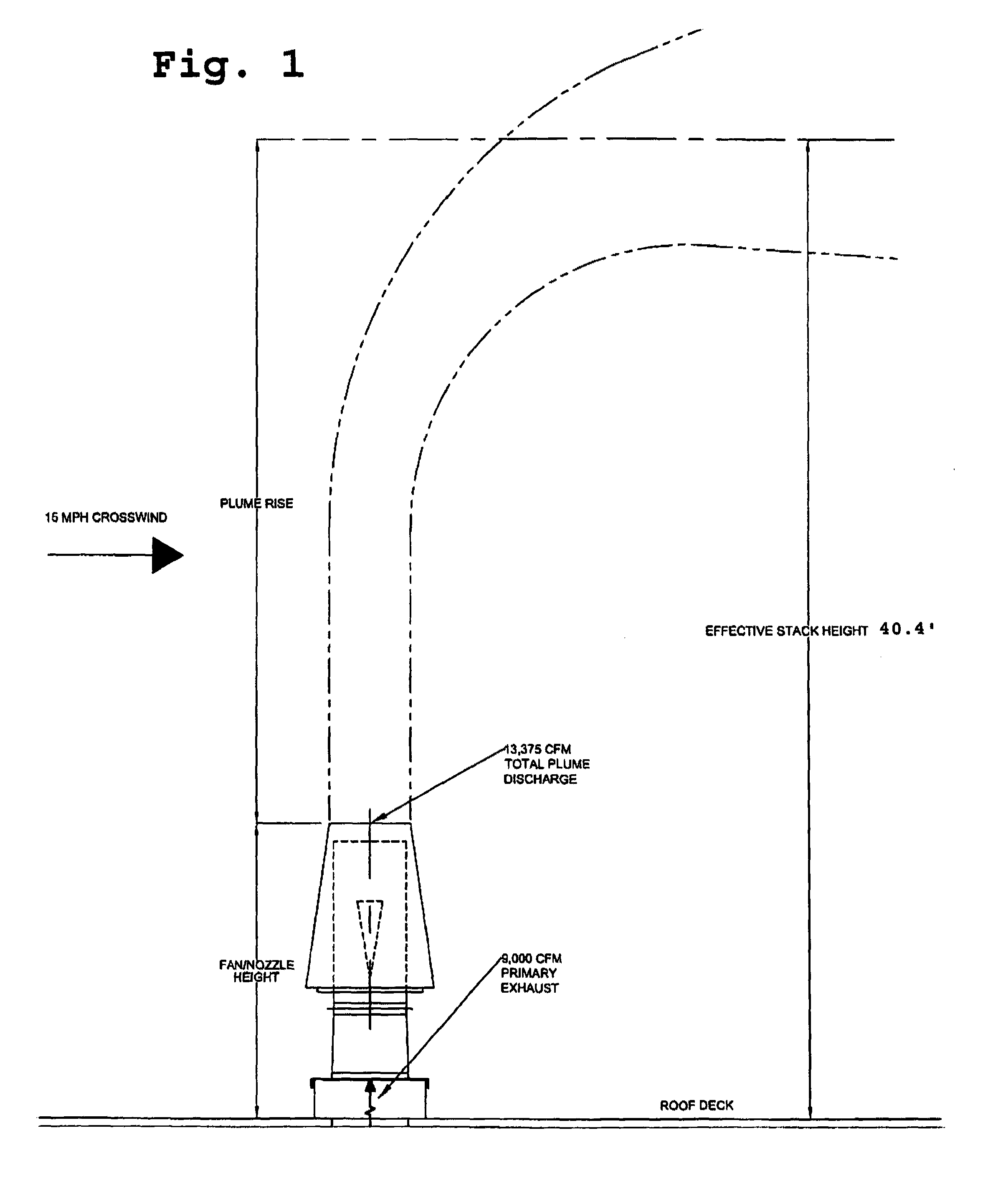
With regard to the first issue, crosswinds not only affect the external plume height, in accordance with the Briggs equations (see below), but they can also interfere with and limit ambient air entrainment into the nozzle, thereby impairing the performance at the nozzle discharge.
Therefore, the industry has not yet recognized the effect of crosswind “blow through” that can take place.
Such crosswind pass-through impairs the performance of the nozzle by diminishing effluent dilution and reducing the nozzle discharge volume, thereby also reducing plume height.
Several other prior art designs offer only nominal windband protection at the nozzle discharge opening, and the consequent exposure to crosswind influence at the nozzle discharge can cause deterioration of plume height performance with “blow through” across the discharge area.
The forgoing features and their associated functions have not been achieved by the prior art in this field.
Moreover, the interconnected “see-through” induced air inlets are subject to crosswind pass-through, which impairs nozzle performance, as explained above.
Therefore, all the prior art aspirating induction nozzles share, in varying degrees, the problem of degraded performance in ambient crosswinds and inefficient mixing of the induced air with the primary exhaust gas.
In addition, they all lack the scalability of the present invention, and hence are not adaptable to retrofitting existing fan / stack installations.

Method used


Image

  • Aspirating induction nozzle
  • Aspirating induction nozzle
  • Aspirating induction nozzle

Examples


Embodiment Construction

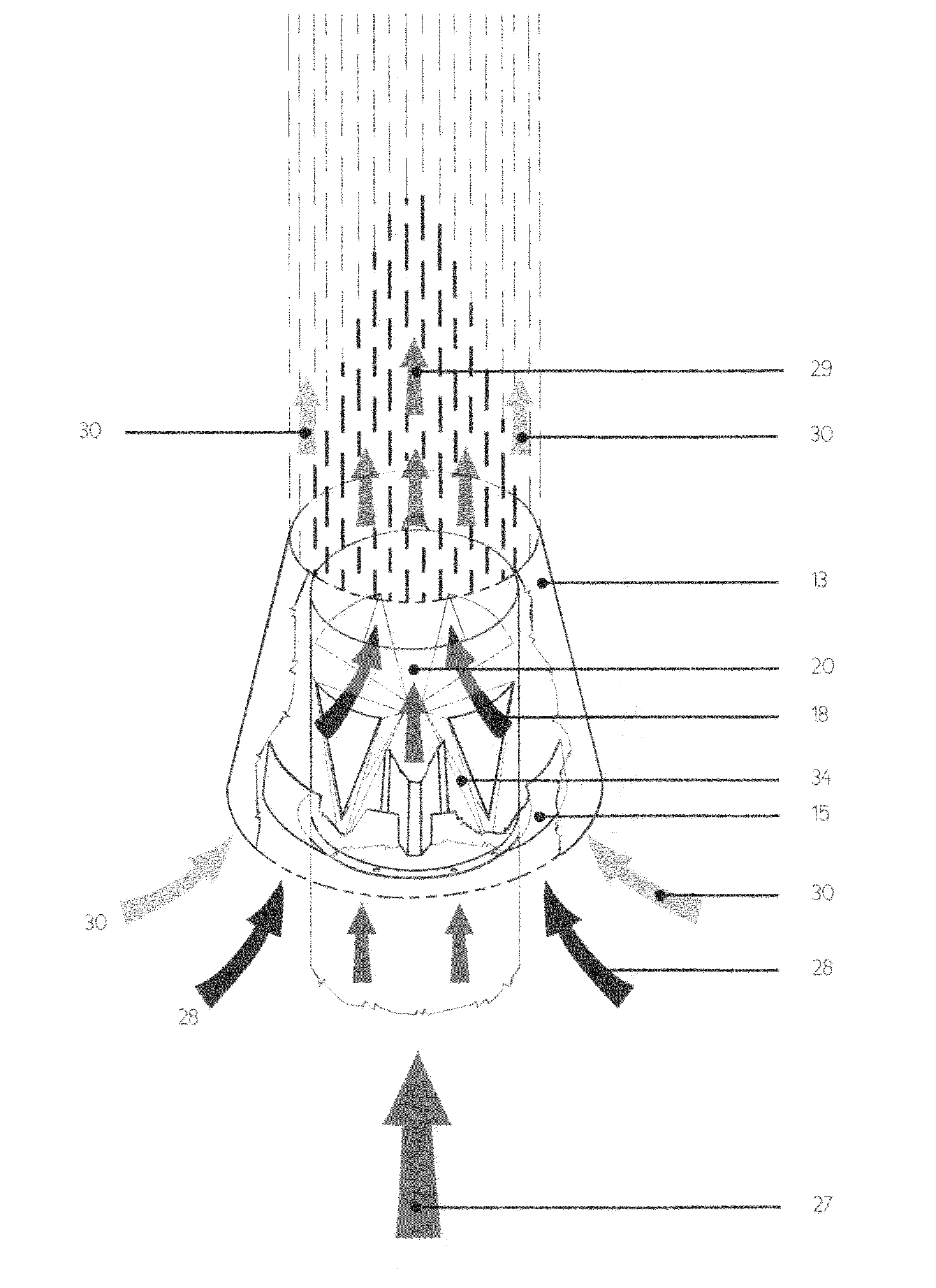
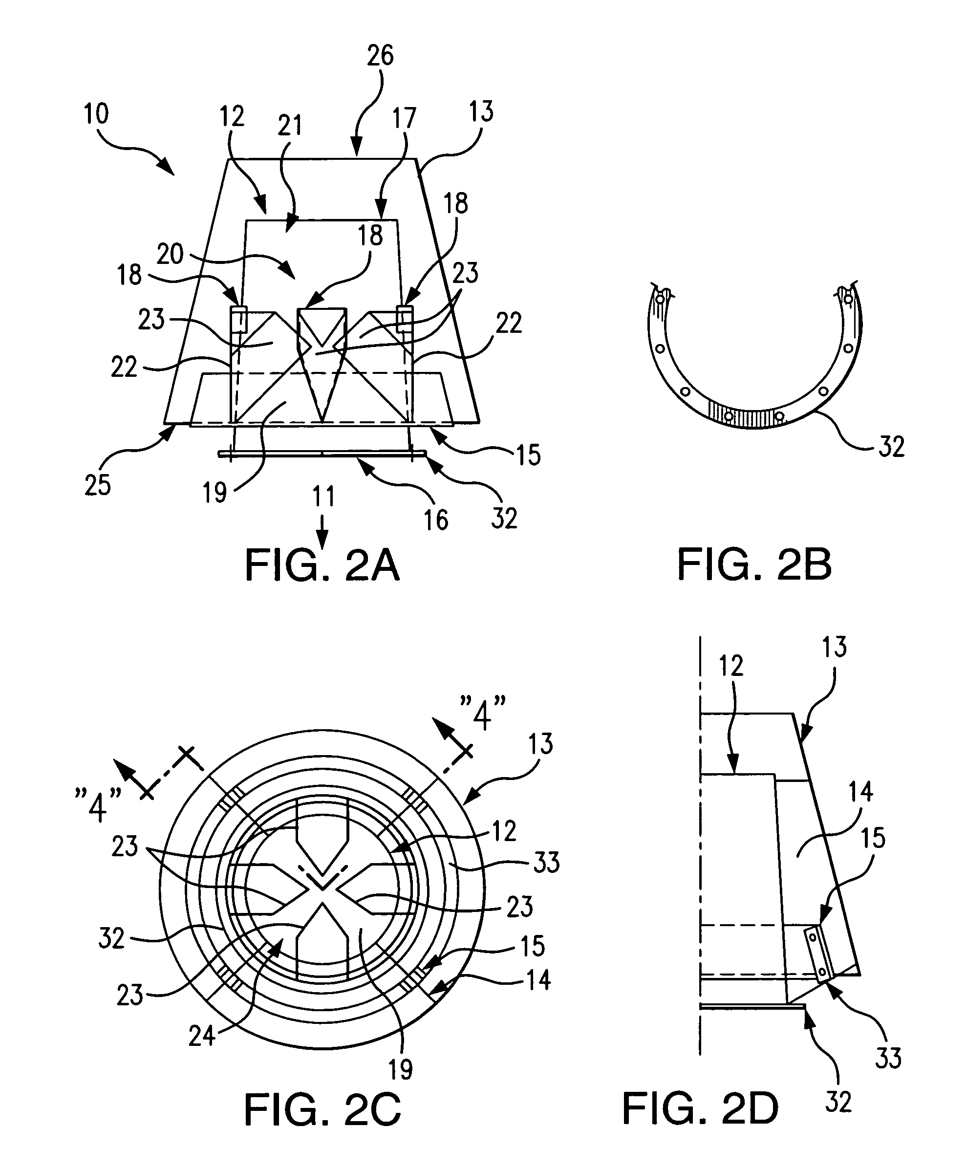
[0055]Referring to FIGS. 2A through 2D, an aspirating induction nozzle assembly 10 is designed for vertical connection to an exhaust gas outlet 11 by means of a connecting flange 32. The nozzle assembly 10 comprises a tubular or frusto-conical central nozzle 12, a long frusto-conical wind band 13, which is attached in annular spaced relation to the central nozzle 12 by multiple mounting brackets 14, and a short frusto-conical guide vane 15, which is attached in annular spaced relation by the mounting brackets 14 between the central nozzle 12 and the wind band 13. Multiple guide vane clips 33 are used to attach the guide vane 15 to the mounting brackets 14.

[0056]The central nozzle 12 comprises a nozzle inlet opening 16 at the lower end, a nozzle discharge opening 17 at the upper end, multiple ambient air induction ports 18, a primary effluent passage 19, a mixing zone 20 and a developing zone 21. Each of the induction ports 18 has an induction inlet 22 and an induction outlet 23. The...


PUM


Abstract

An aspirating induction nozzle for vertical connection to the outlet of a pressurized exhaust gas flow comprises a central nozzle surrounded by a wind band and one or more guide vanes. Ambient air is induced into a mixing zone within the central nozzle to dilute the primary effluent and increase the volumetric discharge flow rate to achieve greater plume lift. The mixing zone within the central nozzle is protected from crosswind influences, which would otherwise diminish plume lift.

Description

BACKGROUND OF THE INVENTION[0001]The present invention relates to the field of exhaust air systems for buildings and / or other enclosed areas, and more particularly, to exhaust discharge nozzles configured to be attached to the outlets of exhaust fans, exhaust ducts and / or stacks, and similar exhaust type equipment / devices and are specifically designed to be installed in the outdoor ambient. The device is designed with a constriction at the outlet to accelerate the exhaust effluent at a high velocity into the atmosphere.[0002]The application of discharge nozzles at the exit point of exhaust systems enhances the performance capability with the specific intent of maximizing the exhaust / effluent dispersion into the upper atmosphere of the unwanted contaminated air and / or effluent gases and vapors from buildings, rooms, and other enclosed spaces. They are able to provide a superior alternative to conventional tall exhaust stacks which are costly to construct and are visually unattractive...

Claims


Application Information

Patent Timeline
Patent Type & Authority Patents(United States)
IPC IPC(8): F23L17/02F24F7/02
CPCF24F7/025F24F13/26
Inventor MORNAN, BRIAN J.BEITZ, FRANK J.
Owner DYNA TECH SALES CORP
Learn More