High power ultrasound wireless transcutaneous energy transfer (US-TET) source

a wireless transcutaneous energy and source technology, applied in the direction of exchanging data chargers, heart stimulators, therapy, etc., can solve the problems of poor efficiency of experiments with curved transducer faces, such as those used for focusing, and limiting the approach

Active Publication Date: 2015-03-10
PIEZO ENERGY TECH
View PDF89 Cites 18 Cited by
  • Summary
  • Abstract
  • Description
  • Claims
  • Application Information

AI Technical Summary

Benefits of technology

[0044]In yet another embodiment of the invention, the transmitter is comprised of a 2-dimensional array of elements arranged on a support, wherein the 2-dimensional array

Problems solved by technology

This approach is limiting for the MCSS application since application of the semi-solid gel is untidy, and over the time of 24/7 operation the gel can dry.
Experiments w

Method used


Image

  • High power ultrasound wireless transcutaneous energy transfer (US-TET) source
  • High power ultrasound wireless transcutaneous energy transfer (US-TET) source
  • High power ultrasound wireless transcutaneous energy transfer (US-TET) source

Examples


Embodiment Construction
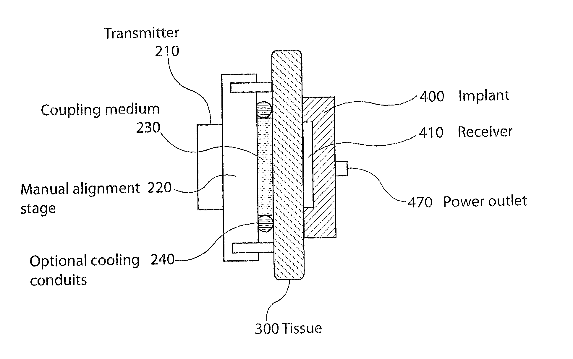
Overall Assembly

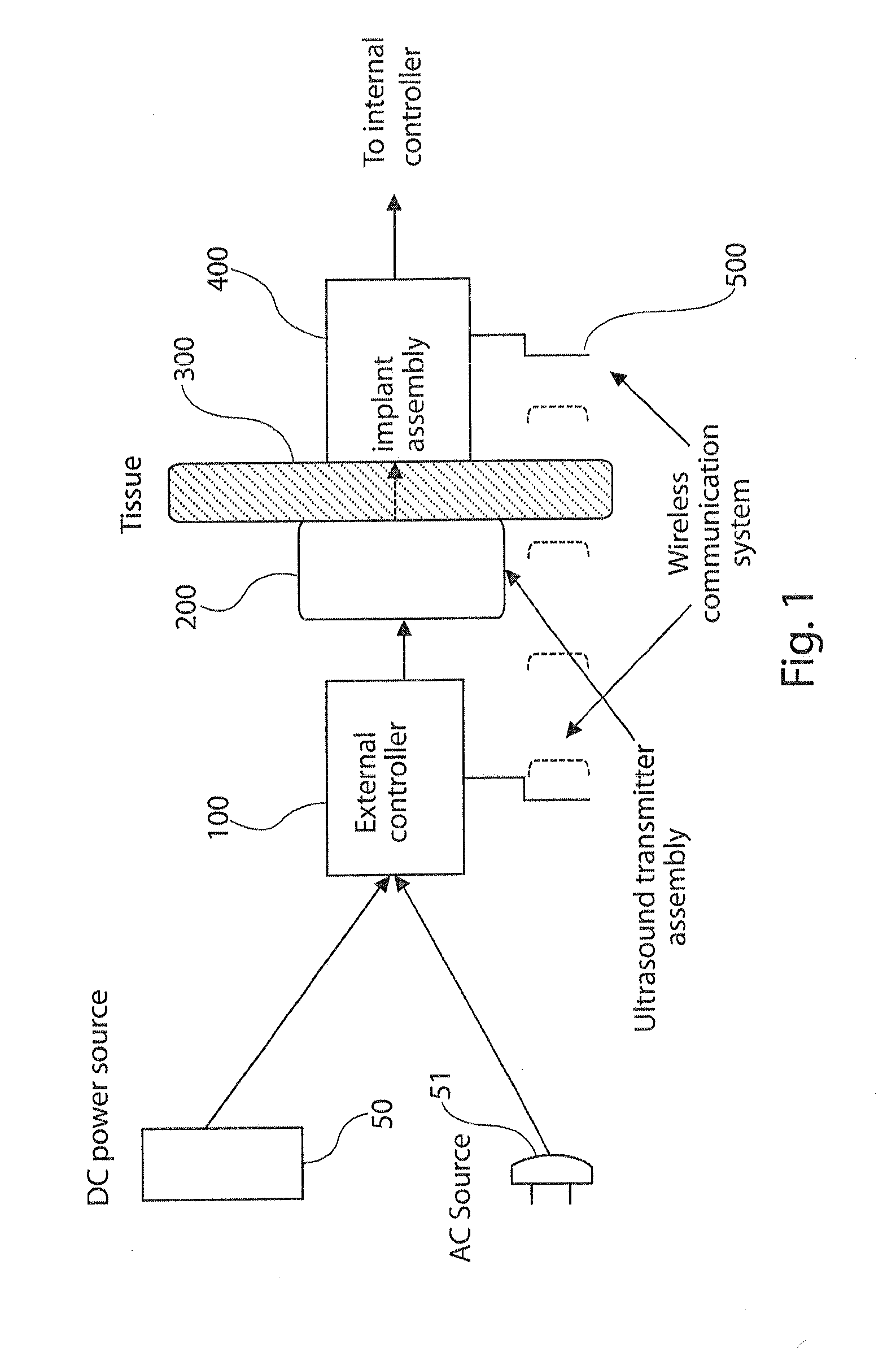
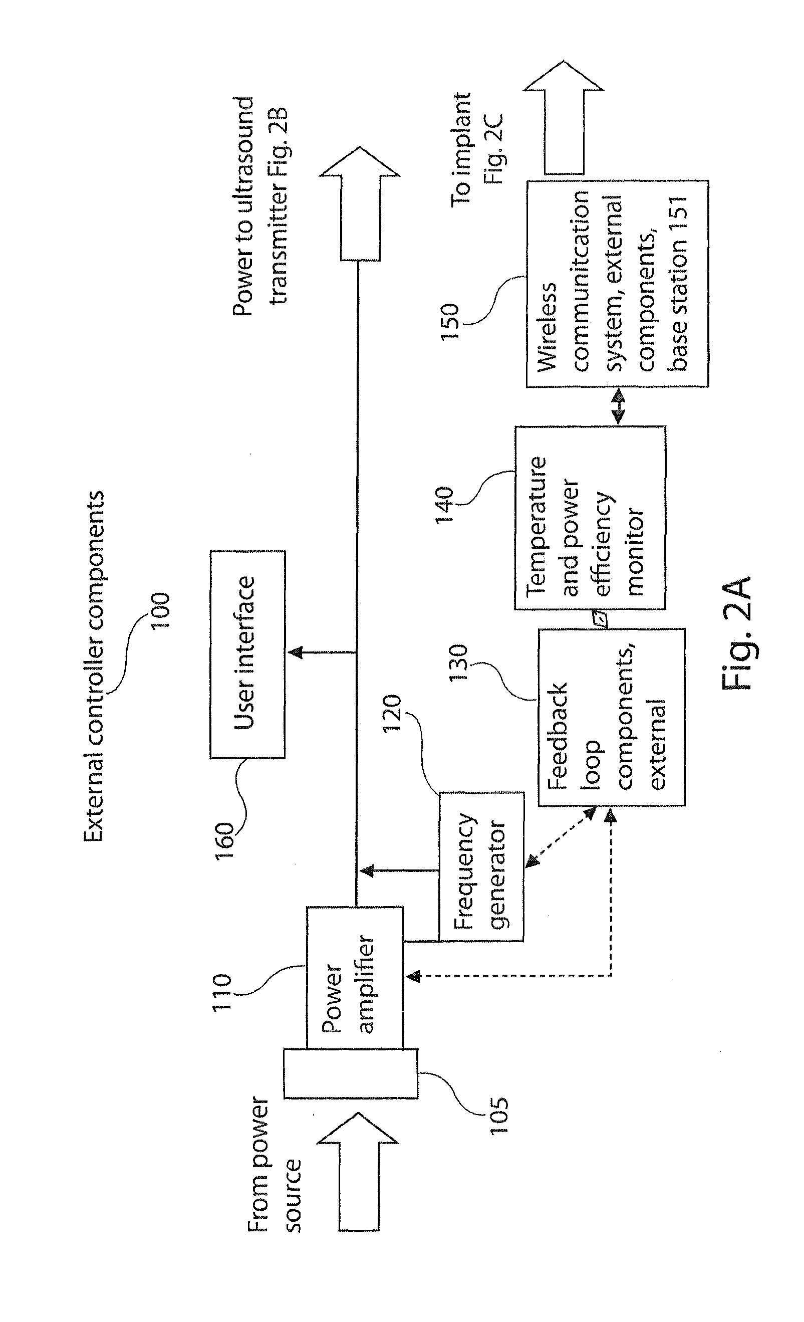
[0061]FIG. 1 is an overall block diagram of an US-TET system in accordance with the present invention. FIGS. 2A, 2B, and 2C are block diagrams the items within the external controller 100, the transmitter assembly 200, and the implant assembly 400 and are discussed in later sections. Referring to FIG. 1, two possible sources of power can operate the system. They are either a direct current (DC) power supply 50 such as a battery, typically worn by the patient, or a conventional room alternating current (AC) source 51. Circuitry within the external controller 100 determines whether the input power is low frequency AC. If so, it proceeds through a DC converter and then through circuitry 120 which converts it to high frequency ultrasound. The external controller 100 controls the level of input power, frequency of the ultrasound, alignment algorithm, and cooling level. These can be operated in two modes, manually and automatically, the latter via a feedback loop 130 and 4...


PUM


Abstract

A bio-implantable energy capture and storage assembly is provided. The assembly includes an acoustic energy transmitter and an acoustic energy receiver. The acoustic energy receiver also functions as an energy converter for converting acoustic energy to electrical energy. An electrical energy storage device is connected to the energy converter, and is contained within a bio-compatible implant for implantation into tissue. The acoustic energy transmitter is separate from the implant, and comprises a substantially 2-dimensional array of transmitters. The acoustic energy converter may also provide conditioned power directly to a load, connected to said energy converter.

Description

CROSS REFERENCE TO RELATED APPLICATION[0001]This application is a continuation-in-part of our co-pending U.S. application Ser. No. 13 / 734,817, filed Jan. 4, 2013, which application in turn claims priority from U.S. Provisional Application Ser. No. 61 / 585,101, filed Jan. 10, 2012, the contents of which are incorporated herein in their entireties.STATEMENT REGARDING FEDERALLY SPONSORED RESEARCH OR DEVELOPMENT[0002]This invention was made with Government support under grants number 1R43EB007421-01A1 and number R44EB007421 awarded by the National Institutes of health. The government has certain rights in the invention.BACKGROUND OF THE INVENTION[0003]The present invention relates to systems for powering implanted devices. The invention has particular utility for systems for powering current implanted devices requiring 24 / 7 operation and tens of watts of electrical power for applications such as heart-assist devices and will be described in connection with such utility, although other ut...

Claims


Application Information

Patent Timeline
IPC IPC(8): A61N1/378A61M60/178A61M60/585A61M60/875
CPCA61M1/127A61M1/1086A61N1/3787A61N1/37217A61M2205/8237H02J50/90H02J50/15H02J7/00034A61M60/178A61M60/875A61M60/585H02J2310/23H02J50/80
Inventor RADZIEMSKI, LEON J.SINGH MAKIN, INDER RAJ
Owner PIEZO ENERGY TECH
Why Eureka
Try Eureka